Hysteresis is a common phenomenon in many physical systems, including electronics. It means the system’s current state depends on its past states. This seemingly peculiar behavior is actually quite useful in various circuits, especially comparators. This article explores hysteresis, its role in operational amplifiers and comparators, and how it’s used to create stable and reliable switching circuits.
Understanding Hysteresis
Hysteresis occurs when a system’s output doesn’t immediately return to its original state when the input is removed. A classic example is found in ferromagnetic materials: after being magnetized, they retain some magnetism even when the external magnetic field is gone. This “memory effect” results in a hysteresis loop when an alternating magnetic field is applied, a characteristic exploited for predictive and stabilizing functions in various applications.
Operational Amplifiers vs. Comparators: The Role of Hysteresis
While seemingly similar, operational amplifiers (op-amps) and comparators have distinct roles and handle hysteresis differently. Op-amps excel in linear operation, amplifying signals with precision. Comparators, on the other hand, are designed for switching, acting as 1-bit analog-to-digital converters (ADCs).
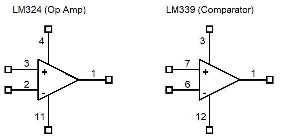
Pin diagrams of an operational amplifier (LM324) and a comparator (LM339).
Although their circuit symbols and pinouts might look alike, the comparator’s open collector output stage is optimized for saturation, driving it to act as a switch. In contrast, the op-amp’s output stage prioritizes linear operation, providing a scaled analog output. Hysteresis plays a vital role in both, influencing their switching behavior.
Hysteresis in Operational Amplifiers
Positive feedback can induce hysteresis in an op-amp, transforming it into a Schmitt trigger circuit. When driven to saturation with a feedback loop, the op-amp’s output saturates, mimicking a comparator. However, this practice isn’t generally recommended due to the op-amp’s unspecified recovery time from saturation, as seen in the common LM324.
Hysteresis in Comparators: What is a Hysteresis Comparator?
A hysteresis comparator utilizes positive feedback to create two distinct switching thresholds. This intentional hysteresis is crucial for clean and stable switching, preventing unwanted transitions caused by noise on the input signal.
Hysteresis in a comparator suppresses unintended switching caused by noise.
This positive feedback creates an upper and a lower threshold voltage for switching. As the input rises, it must cross the upper threshold to trigger the output. When the input falls, it needs to cross the lower threshold to switch the output back. This difference in thresholds, the hysteresis window, prevents oscillations and ensures reliable switching even with noisy inputs. This hysteresis window can also be used to control the duty cycle of the output waveform.
Analyzing Hysteresis with Hysteresis Loop
The hysteresis loop is a graphical representation of a system’s hysteresis. It plots the output against the input, revealing the characteristic loop shape. The width of the loop represents the hysteresis window.
Input and output waveforms (left) and the corresponding hysteresis loop (right).
Factors like input signal frequency, component values in the feedback loop, and the number of cascaded circuits can influence the size of the hysteresis window. Tools like AC sweep simulations and small-signal analysis help designers understand and optimize these effects. Specialized software like PSpice allows for detailed analysis, including plotting B-H curves for magnetic cores.
PSpice’s Model Editor simplifies the management of hysteresis curves.
Cadence’s PSpice Designer for OrCAD provides a comprehensive platform for simulating and analyzing complex circuits with hysteresis, ensuring robust and reliable designs. Contact Cadence to learn more about how their tools can help you master hysteresis in your designs.