In the world of digital electronics, a magnitude digital comparator stands as a fundamental combinational circuit. It’s designed to scrutinize two digital or binary numbers, determining whether one is equal to, less than, or greater than the other. At COMPARE.EDU.VN, we delve into the intricacies of this circuit, offering insights into its operation and applications. Understanding digital comparison and magnitude comparison is crucial for digital system design and analysis.
1. Understanding the Magnitude Comparator
A magnitude comparator is a cornerstone of digital circuit design. At its core, it’s a combinational circuit, a type of logical circuit whose output depends solely on its current input values. Its primary function is to compare two binary numbers to determine their relative magnitudes. The output of this comparison indicates whether one number is greater than, less than, or equal to the other.
These comparators play a pivotal role in various digital systems. They are essential in sorting networks, decision-making circuits, and any application where numerical comparisons must be handled accurately and efficiently. Whether it’s in simple control systems or complex computing environments, the magnitude comparator ensures that numerical data is processed correctly.
The operation of a magnitude comparator involves a meticulous comparison of the bits of two numbers. This process typically starts from the most significant bit (MSB), which carries the highest weight, and progresses towards the least significant bit (LSB). At each bit position, the corresponding bits of the two numbers are compared.
If, at any point, the bit in the first number is greater than the corresponding bit in the second number, the comparator sets its “A > B” output to 1. This immediately signals that the first number is greater, and the comparison process may terminate early. Similarly, if the bit in the second number is greater, the “A < B” output is set to 1, indicating that the first number is less than the second.
If the two corresponding bits are equal, the comparator moves to the next bit position to continue the comparison. This iterative process continues until all bits have been evaluated. If, after comparing all bits, no difference is found, the comparator activates its “A = B” output, signifying that the two numbers are equal.
1.1 Implementation Methods
Magnitude comparators can be implemented using various techniques, each with its own advantages and considerations.
One common approach involves combining basic logic gates such as XOR, AND, and OR gates. This method is straightforward and can be easily customized to suit specific application requirements. By carefully arranging these gates, designers can create a comparator that accurately compares binary numbers and generates the appropriate output signals.
Another implementation method involves using a cascaded arrangement of full adders. Full adders are fundamental building blocks in digital arithmetic circuits, capable of adding two binary digits along with a carry-in bit. By cascading multiple full adders, designers can create a comparator that efficiently compares larger binary numbers.
The choice of implementation method depends on several factors, including speed, complexity, and power consumption. For applications where speed is critical, designers may opt for a more complex implementation that minimizes propagation delays. In contrast, for applications where power consumption is a primary concern, a simpler implementation that consumes less power may be preferred.
At COMPARE.EDU.VN, we understand the challenges in making informed decisions. That’s why we’ve compiled comprehensive comparisons to help you choose the best solutions for your digital circuit designs. Whether you’re weighing speed against power efficiency or evaluating different implementation complexities, our resources are here to guide you.
2. Exploring the 1-Bit Magnitude Comparator
A 1-bit magnitude comparator, as the name suggests, is designed to compare two single-bit binary numbers. This fundamental comparator consists of two inputs, each representing one of the single-bit numbers being compared, and three outputs. These outputs indicate whether the first number is less than, equal to, or greater than the second number.
The simplicity of the 1-bit comparator makes it an ideal building block for more complex comparator circuits. By understanding its operation and characteristics, designers can gain valuable insights into the behavior of larger comparators and digital systems.
2.1 The Truth Table for a 1-Bit Comparator
The truth table provides a comprehensive overview of the behavior of the 1-bit comparator for all possible input combinations. In this table, A and B represent the two single-bit inputs, while A < B, A = B, and A > B represent the corresponding outputs.
| A | B | A < B | A = B | A > B |
|---|---|---|---|---|
| 0 | 0 | 0 | 1 | 0 |
| 0 | 1 | 1 | 0 | 0 |
| 1 | 0 | 0 | 0 | 1 |
| 1 | 1 | 0 | 1 | 0 |
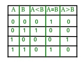
From the truth table, we can derive the logical expressions for each output.
- A > B: This output is true when A is 1 and B is 0. The logical expression is A * B’.
- A = B: This output is true when A and B are either both 0 or both 1. The logical expression is (A’ B’) + (A B).
- A < B: This output is true when A is 0 and B is 1. The logical expression is A’ * B.
2.2 Deriving Logical Expressions
The logical expressions derived from the truth table provide a concise mathematical representation of the behavior of the 1-bit comparator. These expressions can be simplified using Boolean algebra techniques to obtain more efficient implementations.
For example, the expression for A = B can be simplified to (A XOR B)’, where XOR represents the exclusive OR operation. This simplification reduces the number of logic gates required to implement the comparator, leading to lower power consumption and improved performance.
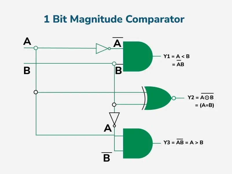
2.3 Implementing the Logic Circuit
Based on the logical expressions, we can implement a logic circuit for the 1-bit comparator using basic logic gates. The circuit consists of AND gates, OR gates, and inverters, interconnected to realize the desired functionality.
The circuit accurately compares the two input bits and generates the corresponding output signals, indicating whether A is less than, equal to, or greater than B.
3. Examining the 2-Bit Magnitude Comparator
A 2-bit magnitude comparator extends the comparison capability to two binary numbers, each consisting of two bits. This type of comparator is more complex than the 1-bit comparator, requiring more inputs and logic gates to implement its functionality.
The 2-bit comparator has four inputs, representing the two bits of each number being compared. It also has three outputs, indicating whether the first number is less than, equal to, or greater than the second number.
3.1 The Truth Table for a 2-Bit Comparator
The truth table for the 2-bit comparator lists all possible combinations of the four input bits and the corresponding output values. This table is essential for understanding the behavior of the comparator and deriving its logical expressions.
| A1 | A0 | B1 | B0 | A < B | A = B | A > B |
|---|---|---|---|---|---|---|
| 0 | 0 | 0 | 0 | 0 | 1 | 0 |
| 0 | 0 | 0 | 1 | 1 | 0 | 0 |
| 0 | 0 | 1 | 0 | 1 | 0 | 0 |
| 0 | 0 | 1 | 1 | 1 | 0 | 0 |
| 0 | 1 | 0 | 0 | 0 | 0 | 1 |
| 0 | 1 | 0 | 1 | 0 | 1 | 0 |
| 0 | 1 | 1 | 0 | 1 | 0 | 0 |
| 0 | 1 | 1 | 1 | 1 | 0 | 0 |
| 1 | 0 | 0 | 0 | 0 | 0 | 1 |
| 1 | 0 | 0 | 1 | 0 | 0 | 1 |
| 1 | 0 | 1 | 0 | 0 | 1 | 0 |
| 1 | 0 | 1 | 1 | 1 | 0 | 0 |
| 1 | 1 | 0 | 0 | 0 | 0 | 1 |
| 1 | 1 | 0 | 1 | 0 | 0 | 1 |
| 1 | 1 | 1 | 0 | 0 | 0 | 1 |
| 1 | 1 | 1 | 1 | 0 | 1 | 0 |
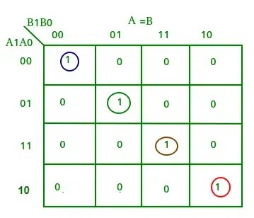
3.2 K-Map Simplification
To simplify the logical expressions for the 2-bit comparator, we can use Karnaugh maps (K-maps). K-maps are graphical tools that facilitate the simplification of Boolean expressions by identifying and eliminating redundant terms.
3.2.1 K-Map for A > B
The K-map for the A > B output is constructed by mapping the corresponding entries from the truth table onto a grid. The grid is organized such that adjacent cells differ by only one variable, allowing for easy identification of simplifications.
3.2.2 K-Map for A = B
Similarly, the K-map for the A = B output is constructed by mapping the corresponding entries from the truth table onto a grid. The grid is organized such that adjacent cells differ by only one variable, allowing for easy identification of simplifications.
3.2.3 K-Map for A < B
The K-map for the A < B output is constructed in the same way, allowing for the simplification of its logical expression.
3.3 Logical Expressions from K-Maps
From the K-maps, we can derive the simplified logical expressions for each output.
- A > B: A1 B1′ + A0 B1′ B0′ + A1 A0 * B0′
- A = B: (A0′ B0′ + A0 B0) (A1′ B1′ + A1 B1) = (A0 XNOR B0) (A1 XNOR B1)
- A < B: A1′ B1 + A1′ A0′ B0 + A0′ B1 * B0
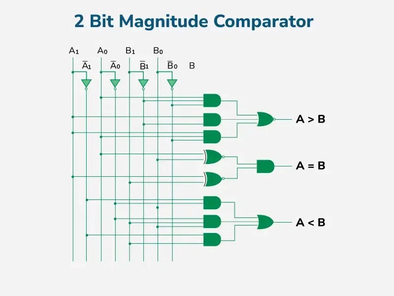
3.4 Implementing the Logic Circuit
Using the simplified logical expressions, we can implement a logic circuit for the 2-bit comparator. This circuit consists of AND gates, OR gates, XOR gates, and inverters, interconnected to realize the desired functionality.
The circuit accurately compares the two 2-bit numbers and generates the corresponding output signals, indicating whether A is less than, equal to, or greater than B.
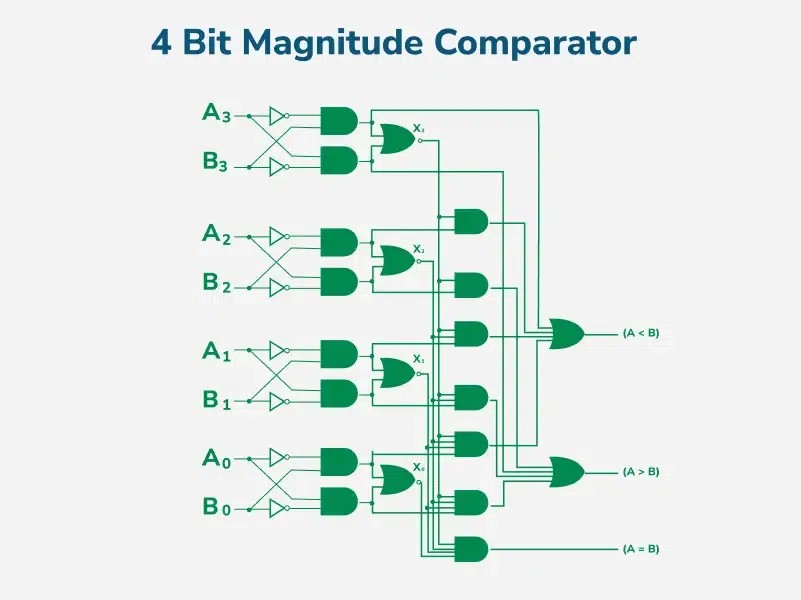
4. Analyzing the 4-Bit Magnitude Comparator
A 4-bit magnitude comparator is used to compare two binary numbers, each consisting of four bits. This type of comparator is more complex than the 2-bit comparator, requiring more inputs and logic gates to implement its functionality.
The 4-bit comparator has eight inputs, representing the four bits of each number being compared. It also has three outputs, indicating whether the first number is less than, equal to, or greater than the second number.
In a 4-bit comparator, the condition of A > B can occur in the following four cases:
- If A3 = 1 and B3 = 0
- If A3 = B3 and A2 = 1 and B2 = 0
- If A3 = B3, A2 = B2 and A1 = 1 and B1 = 0
- If A3 = B3, A2 = B2, A1 = B1 and A0 = 1 and B0 = 0
Similarly, the condition for A < B can occur in the following four cases:
- If A3 = 0 and B3 = 1
- If A3 = B3 and A2 = 0 and B2 = 1
- If A3 = B3, A2 = B2 and A1 = 0 and B1 = 1
- If A3 = B3, A2 = B2, A1 = B1 and A0 = 0 and B0 = 1
The condition of A = B is only possible when all the individual bits of one number exactly coincide with the corresponding bits of another number.
4.1 Logical Expressions for the 4-Bit Comparator
Based on the above statements, the logical expressions for each output can be expressed as follows:
- A > B: A3 B3′ + (A3 XNOR B3) A2 B2′ + (A3 XNOR B3) (A2 XNOR B2) A1 B1′ + (A3 XNOR B3) (A2 XNOR B2) (A1 XNOR B1) A0 B0′
- A < B: A3′ B3 + (A3 XNOR B3) A2′ B2 + (A3 XNOR B3) (A2 XNOR B2) A1′ B1 + (A3 XNOR B3) (A2 XNOR B2) (A1 XNOR B1) A0′ B0
- A = B: (A3 XNOR B3) (A2 XNOR B2) (A1 XNOR B1) * (A0 XNOR B0)
4.2 Implementing the Logic Circuit
Using these Boolean expressions, we can implement a logic circuit for this comparator.
4.3 N-Bit Comparator
For an n-bit comparator:
- Total combinations = 2^(2n)
- Equal combinations (A = B) = 2^n
- Unequal combinations = 2^(2n) – 2^n
- Greater (A > B) combinations = Less (A < B) combinations = (2^(2n) – 2^n) / 2
5. Cascading Comparators for Larger Comparisons
When the task involves comparing binary numbers larger than four bits, a technique called cascading comparators is employed. This method involves connecting two or more 4-bit comparators to extend the comparison operation to the desired number of bits.
In a cascading configuration, the outputs of the lower-order comparator are connected to the corresponding inputs of the higher-order comparator. This arrangement allows the comparators to work together, effectively comparing the larger binary numbers.
By cascading comparators, designers can easily scale the comparison capability to accommodate various bit widths. This modular approach simplifies the design process and allows for efficient implementation of complex comparison systems.
6. Applications of Comparators in Digital Systems
Comparators find widespread use in digital systems, enabling a variety of applications across diverse fields.
- Central Processing Units (CPUs) and Microcontrollers (MCUs): Comparators are essential components in CPUs and MCUs, where they are used for decision-making, address decoding, and control operations.
- Control Applications: In control applications, comparators are used to compare physical variables such as temperature, position, and speed with reference values. This allows for precise control and regulation of various systems.
- Process Controllers and Servo Motor Control: Comparators are used in process controllers to maintain desired process parameters and in servo motor control systems to ensure accurate positioning.
- Password Verification and Biometric Applications: Comparators play a crucial role in password verification systems and biometric applications, where they are used to compare stored data with input data for authentication purposes.
7. Advantages of Using Comparators
Comparators offer several advantages that make them attractive for use in digital systems.
- Simplicity and Efficiency: Comparators are simple and efficient for comparing binary values, making them ideal for high-speed applications.
- Fast Decision-Making: Comparators enable fast decision-making in digital circuits, allowing for quick responses to changing conditions.
- Easy Integration: Comparators can be easily integrated into complex systems such as processors and arithmetic units, enhancing their versatility.
- Modular Design: The modular design of comparators allows them to be scaled for comparing multi-bit numbers, providing flexibility in system design.
8. Limitations to Consider
Despite their advantages, comparators also have some limitations that designers should consider.
- Bit Width Limitations: Comparators have a limit on the number of bits they can compare, requiring cascading for larger bit widths.
- Increased Complexity for Large Bits: Implementing comparators for large bit widths can lead to more complex circuits, increasing design effort and cost.
- Power Consumption: Power consumption increases with the complexity of the circuit, which can be a concern in power-sensitive applications.
At COMPARE.EDU.VN, we recognize the importance of understanding both the strengths and weaknesses of comparators. Our resources provide in-depth analyses of different comparator designs, helping you make informed decisions about which solutions are best suited to your specific needs. Whether you’re optimizing for speed, minimizing power consumption, or balancing complexity with performance, our comprehensive comparisons are here to guide you.
9. Conclusion: The Role of Magnitude Comparators in Digital Logic
Magnitude comparators play a vital role in digital logic systems, enabling the comparison of binary numbers for decision-making and control purposes. Their simplicity, efficiency, and versatility make them essential components in numerous applications. While comparators have limitations in dealing with larger bit widths and power consumption, their advantages outweigh these drawbacks in many scenarios.
As technology advances, comparators will continue to evolve, offering improved performance and functionality. These advancements will further solidify their position as fundamental building blocks in digital systems.
At COMPARE.EDU.VN, we are committed to providing you with the most up-to-date information and resources on magnitude comparators and other digital logic components. Whether you are a student learning the basics or a professional designing complex systems, our website is your go-to source for comprehensive comparisons and expert insights.
Make Informed Decisions with COMPARE.EDU.VN
Navigating the complexities of digital electronics can be challenging. That’s why COMPARE.EDU.VN is here to help. We offer detailed, objective comparisons of various digital components, including magnitude comparators, to assist you in making informed decisions. Our goal is to simplify the decision-making process by providing clear, concise, and comprehensive information.
Whether you’re comparing different implementation methods, evaluating the performance of various comparator designs, or exploring the trade-offs between speed and power consumption, COMPARE.EDU.VN has you covered. Our resources include detailed specifications, performance benchmarks, and expert reviews, ensuring you have all the information you need at your fingertips.
Ready to make smarter choices? Visit COMPARE.EDU.VN today to explore our comprehensive comparisons and start making decisions with confidence. Contact us at 333 Comparison Plaza, Choice City, CA 90210, United States, or reach out via WhatsApp at +1 (626) 555-9090. Let COMPARE.EDU.VN be your trusted partner in digital electronics.
10. Frequently Asked Questions about Magnitude Comparators
10.1 What are the main types of comparators in digital electronics?
In digital electronics, the primary types of comparators include identity comparators, which determine if two inputs are exactly the same, and magnitude comparators, which determine the relative magnitude of two numerical inputs.
10.2 What is a 4-bit magnitude comparator?
A 4-bit magnitude comparator is a digital circuit that compares two 4-bit binary numbers to determine if one is greater than, less than, or equal to the other. It’s a fundamental component in digital systems requiring numerical comparisons.
10.3 What is the primary application of a comparator circuit?
The most common application of a comparator is to compare a voltage or digital signal against a stable reference. This is crucial in control systems, signal processing, and analog-to-digital conversion.
10.4 How does a magnitude comparator work?
A magnitude comparator works by comparing the bits of two binary numbers, starting from the most significant bit (MSB). It determines the relative magnitudes of the numbers and outputs a signal indicating whether one is greater than, less than, or equal to the other.
10.5 What logic gates are commonly used in magnitude comparators?
Magnitude comparators commonly use a combination of logic gates such as AND, OR, XOR, and XNOR gates to perform bitwise comparisons and generate the appropriate output signals.
10.6 How can I cascade comparators to compare larger bit numbers?
To compare larger bit numbers, you can cascade multiple comparators by connecting the outputs of lower-order comparators to the inputs of higher-order comparators. This allows for comparison of binary numbers with lengths beyond the bit width of a single comparator.
10.7 What are the key advantages of using magnitude comparators in digital design?
Key advantages include the ability to perform fast and accurate numerical comparisons, simplicity in design, and ease of integration into larger digital systems.
10.8 What are the limitations of magnitude comparators?
Limitations include increased complexity and power consumption for larger bit widths, as well as the need for cascading to compare numbers beyond the comparator’s bit width.
10.9 In what kind of applications are magnitude comparators typically used?
Magnitude comparators are typically used in applications such as CPUs, microcontrollers, process controllers, servo motor control systems, password verification systems, and biometric devices.
10.10 How do I choose the right comparator for my application?
Choosing the right comparator depends on factors such as the number of bits to be compared, the required speed and accuracy, power consumption constraints, and the complexity of the overall system design. compare.edu.vn offers detailed comparisons to help you make the best choice for your specific needs.