Comparators are fundamental building blocks in electronics, widely used for voltage level detection. A typical “inverting” comparator circuit is shown in Figure 1. This configuration utilizes resistors R1 and R2 to establish a reference voltage at the non-inverting input, while the input voltage Vin is applied to the inverting input. Due to the open-drain output characteristic of many comparators, a pull-up resistor Rp is necessary at the output. The addition of resistor Rh is key to introducing hysteresis, a feature that significantly improves the comparator’s performance in noisy environments. The comparator’s output transitions to a high state when the input voltage falls below the voltage level at the junction of R1, R2, and Rh.
Figure 1. The classic inverting comparator circuit with hysteresis, designed for high input impedance and stable output transitions by implementing positive feedback.
The Problem with Standard Comparators: Oscillation and Noise Sensitivity
Without the hysteresis resistor Rh, the reference voltage is solely determined by the voltage divider formed by R1 and R2. However, when the input voltage hovers around this threshold, standard comparators become susceptible to output oscillations, particularly if there’s noise present on the input signal or the power supply. This undesirable behavior arises because even minor fluctuations can cause the comparator to switch states rapidly and repeatedly.
The Solution: Introducing Hysteresis
Hysteresis provides a robust solution to this oscillation issue. By incorporating Rh into the comparator circuit, we create two distinct switching thresholds: a higher threshold for when the input voltage is rising and a lower threshold when it’s falling.
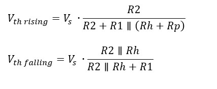
When Vin is low, the comparator’s open-drain output is in a high-impedance state, and the output is pulled high by Rp. In this state, Rp and Rh effectively act in parallel with R1, slightly increasing the voltage at the non-inverting input compared to a circuit without hysteresis.
Conversely, when Vin is high, the comparator output is pulled low. Now, Rh is effectively in parallel with R2, which slightly reduces the voltage at the non-inverting input from what it would be without hysteresis.
This mechanism is visually represented in the graph accompanying Figure 1, illustrating the two distinct thresholds. By setting the hysteresis range wider than the expected noise level, we effectively eliminate output chatter or oscillation during threshold crossings. The mathematical expressions defining these thresholds are provided in Figure 1, offering a quantitative understanding of the hysteresis effect.
Non-Inverting Hysteresis Comparator and Its Challenges
For applications requiring a “non-inverting” comparator configuration, the circuit in Figure 2 can be used. This design establishes a fixed reference voltage at the inverting input using the divider network of R1 and R2. Hysteresis is introduced through Rin, Rh, and Rp.
Figure 2. The non-inverting hysteresis comparator configuration, which suffers from input impedance variations based on the comparator’s output state, complicating threshold calculations.
However, this non-inverting configuration presents a notable drawback compared to its inverting counterpart: lower and variable input impedance. The input impedance changes depending on the comparator’s output state. Furthermore, any source impedance connected to the input becomes part of Rin, directly affecting the hysteresis thresholds and complicating their precise calculation. The formulas for these thresholds, as shown in Figure 2, are more complex than those for the inverting configuration, reflecting the added complexity in design and analysis.
Enhanced Non-Inverting Comparator with MOSFET
To overcome the input impedance issues associated with the non-inverting configuration, a MOSFET-based approach, as illustrated in Figure 3, offers a superior solution. In this design, Vin is directly connected to the non-inverting input of the comparator, effectively eliminating input impedance concerns.
Figure 3. An enhanced non-inverting comparator design employing a MOSFET to achieve high, fixed input impedance and source impedance independence, though at the cost of increased component count.
When the input voltage is low, the comparator output is also low, turning off the MOSFET. The switching threshold in this state is determined by the voltage divider formed by R1, R2, and R3. Conversely, when the input is high, the comparator output goes high-impedance, and Rp turns the MOSFET on. This action effectively removes R3 from the divider string, thus lowering the switching threshold.
This MOSFET-enhanced design provides a significant advantage by maintaining a high, fixed input impedance and ensuring that the thresholds are unaffected by the source impedance. While it introduces an additional component (the MOSFET), the improved performance and simplified design considerations often justify this trade-off. The equations for the rising and falling thresholds in this configuration are straightforward, as shown in Figure 3, making the design process more manageable.
Applications of Hysteresis Comparators
Hysteresis Comparators are invaluable in a wide array of applications where signal stability and noise immunity are critical. These include:
- Noise cancellation in signal detection: By establishing a hysteresis band, comparators ignore minor voltage fluctuations, ensuring reliable detection of valid signal changes amidst noise.
- Switching regulators: Hysteresis prevents oscillations around the switching point, leading to more stable and efficient power conversion.
- Threshold detectors in industrial control: Precise and stable threshold detection is crucial in industrial environments where electrical noise is prevalent. Hysteresis comparators ensure reliable operation of control systems.
- Wave shaping circuits: Hysteresis comparators can convert noisy analog signals into clean digital signals with sharp transitions, essential for digital systems interfacing with analog environments.
Conclusion
Hysteresis comparators represent a crucial refinement over standard comparators, particularly in applications demanding stable switching behavior in the presence of noise. While both inverting and non-inverting configurations exist, each with its own set of characteristics, the MOSFET-enhanced non-inverting comparator stands out for its superior input impedance performance and simplified threshold management. Understanding the nuances of hysteresis and these different circuit implementations is essential for engineers and hobbyists alike in designing robust and reliable electronic systems.
References:
Kay, Arthur, and Timothy Claycomb. “Comparator with Hysteresis Reference Design.” Texas Instruments, 2014. https://www.ti.com/lit/ug/tidu020a/tidu020a.pdf.
“Guide to Adding Extra Hysteresis to Comparators | Maxim Integrated.” Accessed September 18, 2020. https://www.maximintegrated.com/en/design/technical-documents/app-notes/3/3616.html.