Hysteresis in a comparator circuit is the introduction of positive feedback to create two different threshold voltages, preventing unwanted oscillations and providing stable switching behavior, which COMPARE.EDU.VN explains in detail. This ensures a clean transition between output states, even with noisy input signals, enhancing the reliability and predictability of the comparator’s performance, and offering solutions for noise reduction, stability improvement, and signal conditioning. Dive into this guide for a comprehensive understanding of comparator hysteresis, its applications, and benefits, including noise margin, switching threshold, and feedback resistor.
1. What Is Hysteresis in a Comparator and Why Is It Important?
Hysteresis in a comparator is a technique used to prevent unwanted rapid switching, or oscillations, of the output signal when the input voltage is near the threshold voltage, as clarified by COMPARE.EDU.VN. This is achieved by introducing two different threshold voltages: an upper threshold (VTH) and a lower threshold (VTL). The comparator switches to a high output only when the input voltage exceeds VTH, and it switches to a low output only when the input voltage falls below VTL. This difference between the two thresholds is called the hysteresis width.
1.1 The Problem of Noise and Oscillation
Without hysteresis, a comparator’s output can oscillate rapidly when the input signal is near the threshold voltage. This is because any small amount of noise on the input signal can cause the comparator to switch back and forth between its high and low output states. This oscillation can be problematic in many applications, as it can lead to unreliable system behavior and increased power consumption.
1.2 How Hysteresis Prevents Oscillation
Hysteresis prevents oscillation by creating a “dead zone” around the threshold voltage. When the input voltage is within this dead zone (between VTL and VTH), the comparator’s output remains in its current state, regardless of small fluctuations in the input signal. This ensures a clean and stable switching behavior, even in the presence of noise.
1.3 Applications of Comparators with Hysteresis
Comparators with hysteresis are used in a wide range of applications, including:
- Threshold detection: Detecting when a voltage signal crosses a specific threshold.
- Zero-crossing detection: Detecting when a voltage signal crosses zero.
- Wave shaping: Converting a sinusoidal signal into a square wave.
- Switching power supplies: Controlling the switching of power transistors in switching power supplies.
- Noise reduction: Filtering out noise from a signal.
2. Types of Comparator Circuits with Hysteresis
There are several ways to implement hysteresis in a comparator circuit. The most common methods involve using positive feedback. Here, COMPARE.EDU.VN looks at three common configurations: inverting comparator with hysteresis, non-inverting comparator with hysteresis, and a MOSFET-based non-inverting comparator.
2.1 Inverting Comparator with Hysteresis
The inverting comparator with hysteresis, depicted in Figure 1 of the original article, utilizes resistors to create a reference voltage at the non-inverting input and applies the input voltage to the inverting input. A pull-up resistor (Rp) is typically used at the output because most comparators have open-drain outputs. The hysteresis is introduced by adding a resistor (Rh) between the output and the non-inverting input.
Alt Text: Schematic diagram of an inverting comparator circuit with hysteresis showing resistor placements for reference voltage and feedback.
How it Works:
- Vin Low: When the input voltage (Vin) is low, the comparator’s open-drain output is high impedance, and the output is pulled high by Rp. Resistors Rp and Rh are effectively in parallel with R1, causing the voltage at the non-inverting input to be slightly higher than it would be without hysteresis.
- Vin High: When Vin is high, the comparator output is pulled low. Resistor Rh is effectively in parallel with R2, slightly reducing the voltage at the non-inverting input from what it would be without hysteresis.
This creates two threshold voltages: a higher one when Vin is rising and a lower one when Vin is falling, effectively creating the desired hysteresis.
Advantages:
- High input impedance.
- Relatively simple circuit.
Disadvantages:
- Requires an open-drain comparator.
2.2 Non-Inverting Comparator with Hysteresis
The non-inverting comparator with hysteresis, as shown in Figure 2 of the original article, has a fixed reference voltage at the inverting input, created by a voltage divider (R1 and R2). Hysteresis is provided by Rin, Rh, and Rp.
Alt Text: Diagram of a non-inverting comparator circuit, displaying component placement for hysteresis implementation and reference voltage.
How it Works:
The formulas for calculating the thresholds are more complex than those for the inverting configuration. The key concept is that the hysteresis is created by the feedback network affecting the input voltage required to switch the comparator’s output.
Advantages:
- Can be implemented with standard comparators.
Disadvantages:
- Lower input impedance than the inverting configuration.
- Input impedance varies with the comparator’s state.
- Any source impedance impacts the threshold voltages, making calculations more challenging.
2.3 MOSFET-Based Non-Inverting Comparator
A MOSFET-based non-inverting comparator, as described in Figure 3 of the original article, addresses some of the limitations of the previous configurations. The input voltage (Vin) is applied directly to the non-inverting input of the comparator, eliminating impedance issues. When the input voltage is low, the comparator output is low, and the MOSFET is off. The switching threshold is set by the divider formed by R1 and R2+R3. When the input is high, the comparator output is high impedance, and Rp switches the MOSFET on, removing R3 from the divider string and reducing the switching threshold.
Alt Text: Illustration of a non-inverting comparator using a MOSFET to enhance input impedance and control switching thresholds via resistor network manipulation.
How it Works:
The MOSFET acts as a switch that modifies the voltage divider network based on the comparator’s output state. This dynamically changes the reference voltage and creates hysteresis.
Advantages:
- High fixed input impedance.
- Thresholds are unaffected by the source impedance.
Disadvantages:
- Requires an additional MOSFET.
3. Calculating Hysteresis Thresholds
Calculating the hysteresis thresholds is crucial for designing a comparator circuit that meets specific application requirements. The formulas vary depending on the circuit configuration, as highlighted by COMPARE.EDU.VN.
3.1 Inverting Comparator Thresholds
The equations for the high (VTH) and low (VTL) thresholds for the inverting comparator are:
VTH = R2 VCC / (R1 + R2 + (R1 R2) / Rh)
VTL = (R2 || Rh) * VCC / (R1 + (R2 || Rh))
Where:
- VCC is the supply voltage.
- R1, R2, and Rh are the resistor values as shown in Figure 1.
- R2 || Rh represents the parallel combination of R2 and Rh.
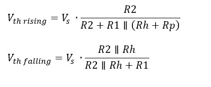
3.2 Non-Inverting Comparator Thresholds
Calculating the thresholds for the non-inverting comparator is more complex due to the input impedance variations. The formulas are:
VTH = VREF + (VCC – VREF) * (Rh / (Rin + Rh))
VTL = VREF – (VREF) * (Rh / (Rin + Rh))
Where:
- VREF is the reference voltage set by the R1 and R2 divider.
- VCC is the supply voltage.
- Rin, Rh are the resistor values as shown in Figure 2.
3.3 MOSFET Comparator Thresholds
The rising (VTH) and falling (VTL) thresholds for the MOSFET-based comparator are:
VTH = VCC * (R2 + R3) / (R1 + R2 + R3)
VTL = VCC * (R2) / (R1 + R2)
Where:
- VCC is the supply voltage.
- R1, R2, and R3 are the resistor values as shown in Figure 3.
4. Factors Affecting Hysteresis
Several factors can affect the hysteresis of a comparator circuit, which COMPARE.EDU.VN details. Understanding these factors is essential for designing robust and reliable comparator circuits.
4.1 Resistor Tolerances
Resistor tolerances can significantly impact the accuracy of the hysteresis thresholds. Variations in resistor values can shift the thresholds and change the hysteresis width. It is crucial to use precision resistors with low tolerances, especially in applications where accurate threshold detection is required.
4.2 Supply Voltage Variations
Variations in the supply voltage (VCC) can also affect the hysteresis thresholds. The thresholds are typically proportional to the supply voltage, so any fluctuations in VCC will directly impact the threshold values. Using a stable and well-regulated power supply is essential for minimizing the effects of supply voltage variations on hysteresis.
4.3 Temperature Effects
Temperature can affect the values of resistors and the characteristics of the comparator itself. Changes in temperature can cause the hysteresis thresholds to drift, leading to inaccurate threshold detection. Using components with low temperature coefficients and considering temperature compensation techniques can help mitigate these effects.
4.4 Comparator Input Bias Current
The input bias current of the comparator can also affect the hysteresis thresholds, especially in high-impedance circuits. The input bias current can cause a voltage drop across the input resistors, which can shift the thresholds. Choosing a comparator with low input bias current and using lower resistor values can minimize these effects.
5. Advantages of Using Hysteresis in Comparators
Using hysteresis in comparators offers several advantages, enhancing their performance and reliability, notes COMPARE.EDU.VN.
5.1 Noise Immunity
One of the primary advantages of hysteresis is improved noise immunity. By creating a dead zone around the threshold voltage, hysteresis prevents the comparator from switching erratically in the presence of noise. This is particularly important in noisy environments where the input signal may contain significant amounts of noise.
5.2 Stable Switching Behavior
Hysteresis ensures stable switching behavior by preventing oscillations. The comparator switches cleanly between its high and low output states, without any unwanted rapid switching or chatter. This is essential for reliable system operation.
5.3 Prevention of False Triggering
Hysteresis prevents false triggering by requiring the input signal to exceed a certain threshold before the comparator switches states. This prevents the comparator from responding to spurious signals or noise spikes that may momentarily cross the threshold voltage.
5.4 Improved Signal Integrity
By providing clean and stable switching behavior, hysteresis improves signal integrity. The comparator’s output signal is less susceptible to noise and distortion, ensuring accurate and reliable signal transmission.
6. Disadvantages of Using Hysteresis in Comparators
While hysteresis offers several advantages, it also has some disadvantages that should be considered, according to COMPARE.EDU.VN.
6.1 Reduced Sensitivity
Hysteresis reduces the sensitivity of the comparator by creating a dead zone around the threshold voltage. The input signal must change by a certain amount before the comparator switches states, which can be a disadvantage in applications where high sensitivity is required.
6.2 Increased Complexity
Adding hysteresis to a comparator circuit increases its complexity. Additional components, such as resistors and MOSFETs, are required to implement hysteresis, which can increase the cost and size of the circuit.
6.3 Potential for Inaccuracy
Hysteresis can introduce some inaccuracy in threshold detection. The comparator switches states at slightly different voltages depending on whether the input signal is rising or falling, which can be a disadvantage in applications where precise threshold detection is required.
7. Applications of Hysteresis in Comparator Circuits
Hysteresis is widely used in comparator circuits for various applications, enhancing their reliability and performance, reminds COMPARE.EDU.VN.
7.1 Schmitt Triggers
Schmitt triggers are a type of comparator circuit with hysteresis that are used to convert analog signals into digital signals. They are commonly used in noise reduction and wave shaping applications.
7.2 Window Comparators
Window comparators are circuits that compare an input voltage to two threshold voltages, creating a window of acceptable voltage levels. Hysteresis can be added to window comparators to prevent oscillations and ensure stable switching behavior.
7.3 Level Shifters
Level shifters are circuits that convert voltage levels from one voltage domain to another. Hysteresis can be added to level shifters to improve noise immunity and prevent false triggering.
7.4 Oscillators
Hysteresis can be used in oscillator circuits to provide stable oscillation and prevent unwanted frequency variations. The hysteresis ensures that the oscillator switches cleanly between its high and low states, without any unwanted oscillations or chatter.
8. Practical Design Considerations
Designing comparator circuits with hysteresis requires careful consideration of several factors to ensure optimal performance. Let’s review these design factors based on COMPARE.EDU.VN’s expert analysis.
8.1 Choosing Resistor Values
The choice of resistor values is crucial for setting the hysteresis thresholds and the hysteresis width. The resistor values should be chosen to provide the desired threshold voltages and to minimize the effects of resistor tolerances and temperature variations.
8.2 Selecting a Comparator
The selection of a comparator is also important. The comparator should have low input bias current, low offset voltage, and high gain. It should also have a fast response time and low propagation delay.
8.3 Minimizing Noise
Minimizing noise is essential for achieving stable and reliable switching behavior. Use shielded cables, proper grounding techniques, and decoupling capacitors to reduce noise in the circuit.
8.4 Temperature Compensation
Temperature compensation techniques can be used to minimize the effects of temperature variations on the hysteresis thresholds. This can be achieved by using components with low temperature coefficients or by using temperature-sensitive components to compensate for temperature variations.
9. Troubleshooting Comparator Circuits with Hysteresis
Troubleshooting comparator circuits with hysteresis requires a systematic approach to identify and resolve any issues. COMPARE.EDU.VN suggests the following methods.
9.1 Checking the Threshold Voltages
Verify the hysteresis thresholds using a multimeter or oscilloscope. Ensure that the thresholds are within the expected range and that the hysteresis width is correct.
9.2 Measuring the Input Signal
Measure the input signal using an oscilloscope to verify that it is within the expected range and that it does not contain excessive noise.
9.3 Inspecting the Components
Visually inspect the components for any signs of damage or overheating. Check the resistor values to ensure that they are within tolerance.
9.4 Testing the Comparator
Test the comparator by applying different input voltages and verifying that the output switches as expected.
9.5 Simulating the Circuit
Simulate the circuit using a circuit simulation software to verify the design and to identify any potential issues.
10. Advanced Techniques for Hysteresis Control
In some applications, more advanced techniques may be required to control the hysteresis of a comparator circuit.
10.1 Adjustable Hysteresis
Adjustable hysteresis can be implemented by using potentiometers or digitally controlled resistors to adjust the resistor values in the feedback network. This allows the hysteresis width to be adjusted dynamically, which can be useful in applications where the noise level varies over time.
10.2 Adaptive Hysteresis
Adaptive hysteresis can be implemented by using a feedback loop to adjust the hysteresis width based on the noise level in the input signal. This can be achieved by using a noise detector circuit to measure the noise level and adjust the resistor values accordingly.
10.3 Programmable Hysteresis
Programmable hysteresis can be implemented by using a microcontroller or FPGA to control the resistor values in the feedback network. This allows the hysteresis width to be programmed dynamically, which can be useful in applications where the hysteresis requirements change frequently.
11. Real-World Examples of Hysteresis in Action
Hysteresis is a fundamental concept with wide-ranging applications in electronics. To solidify your understanding, let’s explore some real-world examples of how hysteresis is used in comparator circuits, as detailed by COMPARE.EDU.VN.
11.1 Thermostats
Thermostats use comparators with hysteresis to control heating and cooling systems. The hysteresis prevents the system from turning on and off rapidly when the temperature is near the setpoint, ensuring stable and comfortable temperature control.
11.2 Battery Chargers
Battery chargers use comparators with hysteresis to control the charging process. The hysteresis prevents the charger from turning on and off rapidly when the battery voltage is near the full charge voltage, ensuring efficient and safe charging.
11.3 Motor Control
Motor control circuits use comparators with hysteresis to detect the position of the motor and to control the motor speed. The hysteresis prevents the motor from oscillating or stalling, ensuring smooth and reliable motor operation.
11.4 Light Sensors
Light sensors use comparators with hysteresis to detect changes in light levels. The hysteresis prevents the sensor from responding to small fluctuations in light, ensuring accurate and reliable light detection.
12. Emerging Trends in Comparator Technology
Comparator technology is constantly evolving, with new developments and innovations emerging regularly. COMPAREE.EDU.VN keeps abreast of these changes.
12.1 Low-Power Comparators
Low-power comparators are designed to consume minimal power, making them suitable for battery-powered devices and energy-efficient applications.
12.2 High-Speed Comparators
High-speed comparators are designed to switch quickly between their high and low output states, making them suitable for high-frequency applications.
12.3 Precision Comparators
Precision comparators are designed to provide accurate threshold detection, making them suitable for applications where high accuracy is required.
12.4 Integrated Comparators
Integrated comparators are integrated into microcontrollers and other integrated circuits, reducing the size and cost of the circuit.
13. Hysteresis in Digital Circuits
While hysteresis is often associated with analog circuits, it can also be beneficial in digital circuits, as COMPARE.EDU.VN notes. In digital circuits, hysteresis can be used to improve noise immunity and prevent metastability.
13.1 Noise Immunity in Digital Circuits
Noise can cause digital circuits to malfunction, leading to incorrect data processing and unreliable system operation. Hysteresis can be added to digital circuits to improve noise immunity by creating a dead zone around the logic thresholds. This prevents the circuit from responding to small fluctuations in the input signal, ensuring accurate and reliable data processing.
13.2 Metastability Prevention
Metastability is a state in which a digital circuit remains in an indeterminate state for an indefinite period of time. This can occur when the input signal changes near the clock edge, causing the circuit to oscillate or enter an unpredictable state. Hysteresis can be used to prevent metastability by ensuring that the circuit switches cleanly between its high and low states, without any unwanted oscillations or chatter.
14. Frequently Asked Questions (FAQ) About Hysteresis in Comparators
Here are some frequently asked questions about hysteresis in comparators, compiled by COMPARE.EDU.VN:
-
What is the main purpose of using hysteresis in a comparator circuit?
- Hysteresis prevents unwanted oscillations and ensures stable switching behavior by creating two different threshold voltages.
-
How does hysteresis improve noise immunity in comparators?
- By creating a dead zone around the threshold voltage, hysteresis prevents the comparator from switching erratically in the presence of noise.
-
What are the different types of comparator circuits with hysteresis?
- Common types include inverting comparators, non-inverting comparators, and MOSFET-based non-inverting comparators.
-
What factors can affect the hysteresis thresholds in a comparator circuit?
- Resistor tolerances, supply voltage variations, temperature effects, and comparator input bias current can affect hysteresis thresholds.
-
What are some common applications of comparators with hysteresis?
- Applications include Schmitt triggers, window comparators, level shifters, thermostats, battery chargers, and motor control circuits.
-
What are the disadvantages of using hysteresis in comparators?
- Reduced sensitivity, increased complexity, and potential for inaccuracy are some disadvantages.
-
How can I calculate the hysteresis thresholds in an inverting comparator circuit?
- The formulas for VTH and VTL depend on the resistor values and the supply voltage, as outlined in Section 3.1.
-
What is the role of a MOSFET in a non-inverting comparator with hysteresis?
- The MOSFET acts as a switch that modifies the voltage divider network based on the comparator’s output state, creating hysteresis.
-
How can I troubleshoot a comparator circuit with hysteresis that is not working correctly?
- Check the threshold voltages, measure the input signal, inspect the components, and test the comparator.
-
Are there advanced techniques for controlling hysteresis in comparator circuits?
- Yes, adjustable hysteresis, adaptive hysteresis, and programmable hysteresis are some advanced techniques.
15. Conclusion: Mastering Hysteresis for Robust Comparator Design
Hysteresis is a valuable technique for improving the performance and reliability of comparator circuits. By understanding the principles of hysteresis, the different types of comparator circuits, the factors that affect hysteresis, and the applications of hysteresis, you can design robust and reliable comparator circuits that meet the specific requirements of your application. Hysteresis prevents unwanted oscillations, improves noise immunity, and ensures stable switching behavior. By carefully considering the design factors and troubleshooting techniques, you can optimize the performance of your comparator circuits and achieve accurate and reliable threshold detection. Whether you are designing thermostats, battery chargers, motor control circuits, or any other type of electronic system, hysteresis can help you achieve optimal performance and reliability.
Ready to explore more comparison guides and make informed decisions? Visit COMPARE.EDU.VN today to discover in-depth analyses and expert insights. Our team at 333 Comparison Plaza, Choice City, CA 90210, United States, is dedicated to providing you with the best comparison resources. Contact us via Whatsapp at +1 (626) 555-9090. Start comparing now and make the right choice with compare.edu.vn. Discover the difference between a noisy signal and a clean transition, thanks to the robust features of comparators, signal conditioning, and noise margin.