A 1-bit comparator is a fundamental digital circuit used to compare two single-bit binary numbers, determining if one is greater than, less than, or equal to the other; you can find more detailed comparisons at COMPARE.EDU.VN. This article dives into the intricacies of 1-bit comparators, exploring their functionality, truth tables, and applications, and also touches on multi-bit comparators and cascading techniques. Unlock more in-depth analysis and comparison insights with advanced circuit design resources.
1. Understanding Magnitude Comparators
A magnitude comparator is a digital circuit designed to compare the magnitudes of two binary numbers. It determines whether one number is greater than, less than, or equal to the other. These circuits are essential in various digital systems for sorting networks, decision-making, and handling numerical comparisons accurately.
The core function of a magnitude comparator involves bit-by-bit comparison, typically starting from the most significant bit (MSB) and proceeding towards the least significant bit (LSB). At each bit position, the comparator assesses the relationship between the corresponding bits of the two numbers. Based on these comparisons, it generates outputs indicating whether the first number is greater than, less than, or equal to the second number.
1.1 N-Bit Comparator
An N-bit comparator expands on the basic principle by comparing two N-bit binary numbers. The circuit compares bits from the MSB to the LSB. If, at any point, the corresponding bits differ, the comparator immediately determines whether A > B or A < B and sets the appropriate output.
If the bits are equal, the comparison moves to the next bit position. If all bits are equal after comparing all positions, the comparator asserts A = B.
1.2 Implementing Magnitude Comparators
Magnitude comparators can be implemented in different ways:
- Using Logic Gates: Combinations of XOR, AND, and OR gates can create comparators.
- Cascaded Full Adders: Full adders can be arranged in a cascaded manner for comparison.
The choice of implementation depends on factors like speed, complexity, and power consumption.
2. Deep Dive: What Is a 1-Bit Comparator?
A 1-bit comparator, also known as a single-bit comparator, is the most basic form of a magnitude comparator. It compares two single-bit binary numbers to determine if one is greater than, less than, or equal to the other. This comparator has two inputs for the two bits being compared and three outputs representing the conditions A > B, A = B, and A < B.
2.1 Truth Table for a 1-Bit Comparator
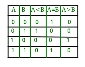
The functionality of a 1-bit comparator is best described by its truth table, which outlines all possible input combinations and their corresponding outputs:
| Input A | Input B | Output A > B | Output A = B | Output A < B |
|---|---|---|---|---|
| 0 | 0 | 0 | 1 | 0 |
| 0 | 1 | 0 | 0 | 1 |
| 1 | 0 | 1 | 0 | 0 |
| 1 | 1 | 0 | 1 | 0 |
2.2 Logical Expressions
From the truth table, we can derive logical expressions for each output:
- A > B: A * B’ (A AND NOT B)
- A = B: (A’ B’) + (A B) (A Ex-NOR B)
- A < B: A’ * B (NOT A AND B)
These expressions form the foundation for the logic circuit implementation of the 1-bit comparator.
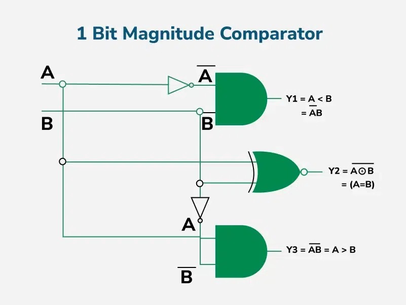
2.3 Circuit Diagram and Explanation
The logic circuit for a 1-bit comparator can be implemented using basic logic gates based on the logical expressions derived from the truth table.
The circuit typically includes:
- AND gate: To implement A > B (A AND NOT B)
- XNOR gate: To implement A = B (A Ex-NOR B)
- AND gate: To implement A < B (NOT A AND B)
- Inverters: To generate the complements of A and B.
By connecting these gates according to the logical expressions, the circuit accurately compares the two input bits and produces the corresponding outputs.
3. Exploring 2-Bit Magnitude Comparators
A 2-bit magnitude comparator compares two 2-bit binary numbers. It has four inputs (two bits for each number) and three outputs (A > B, A = B, A < B).
3.1 Truth Table for a 2-Bit Comparator
The truth table for a 2-bit comparator expands significantly compared to the 1-bit comparator, as it needs to cover all combinations of the four input bits.
| A1 | A0 | B1 | B0 | A > B | A = B | A < B |
|---|---|---|---|---|---|---|
| 0 | 0 | 0 | 0 | 0 | 1 | 0 |
| 0 | 0 | 0 | 1 | 0 | 0 | 1 |
| 0 | 0 | 1 | 0 | 0 | 0 | 1 |
| 0 | 0 | 1 | 1 | 0 | 0 | 1 |
| 0 | 1 | 0 | 0 | 1 | 0 | 0 |
| 0 | 1 | 0 | 1 | 0 | 1 | 0 |
| 0 | 1 | 1 | 0 | 0 | 0 | 1 |
| 0 | 1 | 1 | 1 | 0 | 0 | 1 |
| 1 | 0 | 0 | 0 | 1 | 0 | 0 |
| 1 | 0 | 0 | 1 | 1 | 0 | 0 |
| 1 | 0 | 1 | 0 | 0 | 1 | 0 |
| 1 | 0 | 1 | 1 | 0 | 0 | 1 |
| 1 | 1 | 0 | 0 | 1 | 0 | 0 |
| 1 | 1 | 0 | 1 | 1 | 0 | 0 |
| 1 | 1 | 1 | 0 | 1 | 0 | 0 |
| 1 | 1 | 1 | 1 | 0 | 1 | 0 |
3.2 Deriving Logical Expressions Using K-Maps
Karnaugh maps (K-maps) are used to simplify the Boolean expressions derived from the truth table. Each output (A > B, A = B, A < B) requires its own K-map to minimize the logic required.
3.2.1 K-Map for A > B
From the K-map, the simplified expression for A > B is:
A1B1’ + A1’A0B0’ + A1A0B0’
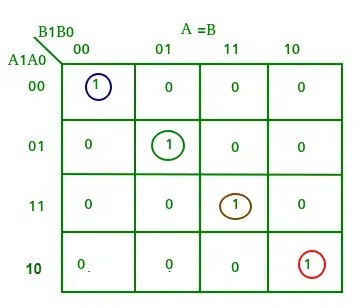
3.2.2 K-Map for A = B
The simplified expression for A = B is:
(A1’ Ex-NOR B1) * (A0 Ex-NOR B0)
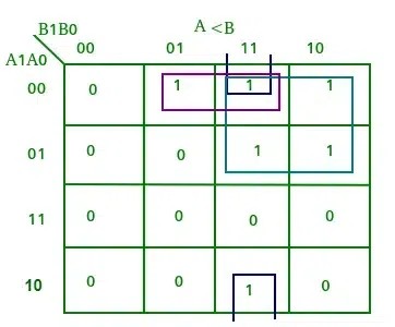
3.2.3 K-Map for A < B
From the K-map, the simplified expression for A < B is:
A1’B1 + A1’A0’B0 + A0’B1B0
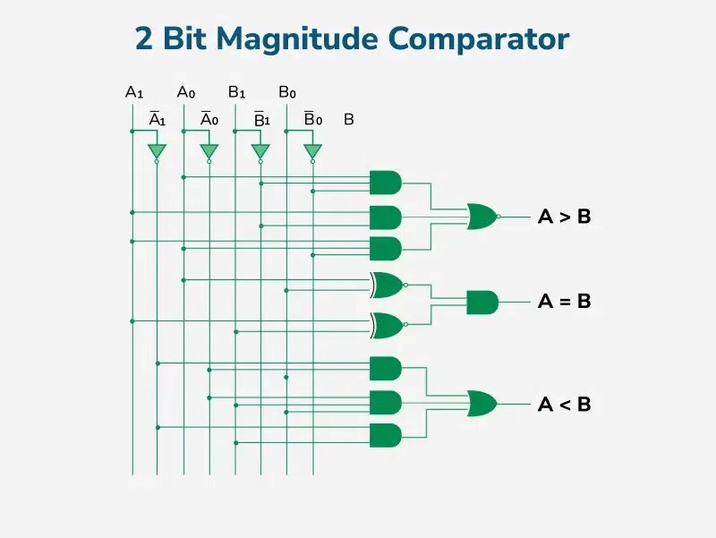
3.3 Circuit Diagram
Based on the simplified Boolean expressions, the logic circuit for a 2-bit magnitude comparator can be implemented using various logic gates.
The circuit includes AND, OR, NOT, and XNOR gates configured to implement the expressions for A > B, A = B, and A < B.
4. Scaling Up: 4-Bit Magnitude Comparators
A 4-bit magnitude comparator compares two 4-bit binary numbers. It has eight inputs (four bits for each number) and three outputs (A > B, A = B, A < B).
4.1 Logic Conditions
The conditions for A > B in a 4-bit comparator are:
- If A3 = 1 and B3 = 0
- If A3 = B3 and A2 = 1 and B2 = 0
- If A3 = B3, A2 = B2 and A1 = 1 and B1 = 0
- If A3 = B3, A2 = B2, A1 = B1 and A0 = 1 and B0 = 0
Similarly, the conditions for A < B are:
- If A3 = 0 and B3 = 1
- If A3 = B3 and A2 = 0 and B2 = 1
- If A3 = B3, A2 = B2 and A1 = 0 and B1 = 1
- If A3 = B3, A2 = B2, A1 = B1 and A0 = 0 and B0 = 1
The condition for A = B is met only when all corresponding bits of the two numbers are equal.
4.2 Logical Expressions
The logical expressions for the outputs are:
- A > B:
A3B3’ + (A3 Ex-NOR B3)A2B2’ + (A3 Ex-NOR B3)(A2 Ex-NOR B2)A1B1’ + (A3 Ex-NOR B3)(A2 Ex-NOR B2)(A1 Ex-NOR B1)A0B0’ - A < B:
A3’B3 + (A3 Ex-NOR B3)A2’B2 + (A3 Ex-NOR B3)(A2 Ex-NOR B2)A1’B1 + (A3 Ex-NOR B3)(A2 Ex-NOR B2)(A1 Ex-NOR B1)A0’B0 - A = B:
(A3 Ex-NOR B3)(A2 Ex-NOR B2)(A1 Ex-NOR B1)(A0 Ex-NOR B0)
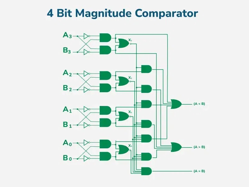
4.3 Circuit Diagram
The logic circuit for a 4-bit magnitude comparator involves a combination of XOR, AND, OR, and NOT gates to implement the above expressions.
5. Cascading Comparators for Larger Bit Widths
When comparing binary numbers with more than four bits, cascading multiple 4-bit comparators is an effective solution. In cascading, the outputs of lower-order comparators are connected to the corresponding inputs of higher-order comparators.
This approach allows for the comparison of binary numbers of any bit length by simply adding more comparator stages.
6. Applications of Comparators
Comparators are used in a variety of applications:
- CPUs and MCUs: In central processing units and microcontrollers.
- Control Systems: For control applications where binary numbers represent physical variables.
- Process Controllers: As process controllers.
- Servo Motor Control: For servo motor control.
- Password Verification: In password verification systems.
- Biometric Applications: In biometric identification systems.
7. Advantages of Comparators
- Simplicity: Simple and efficient for binary value comparisons.
- Speed: Fast decision-making in digital circuits.
- Integration: Easily integrated into complex systems.
- Modularity: Modular design allows for scalable solutions.
8. Disadvantages of Comparators
- Bit Limit: Limited bit comparison capability without cascading.
- Complexity: Complex circuits for large bit comparisons.
- Power Consumption: Power consumption increases with circuit complexity.
9. Key Takeaways
Magnitude comparators are indispensable in digital logic systems for binary number comparisons. While they are efficient for smaller bit widths, larger comparisons may require cascading or more complex designs. Their use in CPUs, control systems, and security applications underscores their importance in modern digital technology.
10. Frequently Asked Questions (FAQs)
- What is a magnitude comparator?
A magnitude comparator is a digital circuit that compares two binary numbers to determine if one is greater than, less than, or equal to the other.
- How does a 1-bit comparator work?
A 1-bit comparator compares two single-bit binary numbers and produces outputs indicating whether the first bit is greater than, equal to, or less than the second bit.
- What are the outputs of a magnitude comparator?
The outputs are A > B, A = B, and A < B, indicating the relationship between the two input numbers.
- What is the difference between a 1-bit and a 2-bit comparator?
A 1-bit comparator compares two single-bit numbers, while a 2-bit comparator compares two 2-bit numbers, requiring a more complex circuit.
- How are K-maps used in designing comparators?
K-maps are used to simplify the Boolean expressions derived from the truth table, reducing the complexity of the logic circuit required for the comparator.
- What is cascading in the context of comparators?
Cascading is the process of connecting multiple comparators to compare binary numbers with bit lengths larger than the capacity of a single comparator.
- Where are comparators used?
Comparators are used in CPUs, control systems, process controllers, servo motor control, password verification, and biometric applications.
- What are the advantages of using comparators?
Comparators are simple, efficient, fast, and easily integrated into complex systems.
- What are the disadvantages of using comparators?
Comparators have limitations in bit comparison without cascading, and complexity and power consumption increase with larger bit comparisons.
- Can comparators be used to compare analog signals?
No, magnitude comparators are designed for digital signals. Analog comparators are used for analog signals.
If you’re finding it challenging to compare different digital components or systems, visit COMPARE.EDU.VN for comprehensive and objective comparisons. We offer detailed analyses of various products, services, and ideas, highlighting the pros and cons of each. Our comparisons include features, specifications, pricing, and user reviews to help you make informed decisions.
Ready to make smarter choices? Head over to COMPARE.EDU.VN today and explore our detailed comparisons to find the perfect fit for your needs. For personalized assistance, contact us at 333 Comparison Plaza, Choice City, CA 90210, United States. You can also reach us via Whatsapp at +1 (626) 555-9090. Visit our website at compare.edu.vn for more information.