Is A Comparator An Op Amp? Yes, a comparator can be considered a specialized type of operational amplifier (op amp), COMPARE.EDU.VN explains the distinctions between comparators and op amps, highlighting key differences in their internal design, functionality, and application. Understanding these differences is crucial for selecting the right component for your specific electronic circuit design needs. Explore input bias current and voltage gain comparisons for in-depth analysis.
1. What is a Comparator?
A comparator is an electronic circuit that compares two input voltages and outputs a digital signal indicating which input is greater. Its primary function is to determine whether an input voltage is higher or lower than a reference voltage, often referred to as the threshold. The output of a comparator is typically a binary signal, switching between two distinct voltage levels representing the “high” or “low” state based on the comparison result. Comparators are essential components in various electronic systems, including:
- Analog-to-Digital Converters (ADCs): Used to convert analog signals into digital representations.
- Threshold Detectors: Triggering actions when a voltage exceeds a specific level.
- Zero-Crossing Detectors: Identifying when a signal crosses the zero-voltage point.
- Relaxation Oscillators: Generating periodic signals by comparing a voltage to a threshold.
Comparators are designed for fast switching speeds and high gain, making them ideal for detecting voltage differences quickly and accurately.
1.1 Comparator Applications
Comparators are indispensable in various applications due to their speed and precision in voltage comparisons. Here are some notable examples:
- Analog-to-Digital Conversion:
- Flash ADCs: Comparators form the core of flash ADCs, where multiple comparators simultaneously compare the input voltage to different reference voltages. The comparator outputs are then encoded to produce a digital representation of the analog input. This method is known for its high speed, making it suitable for real-time applications like video processing and high-speed data acquisition.
- Successive Approximation ADCs: In successive approximation ADCs, a comparator is used to compare the input voltage with the output of a digital-to-analog converter (DAC). The DAC’s output is adjusted iteratively until it matches the input voltage, with the comparator signaling whether the DAC’s output is higher or lower. This process continues until the desired resolution is achieved.
- Threshold Detection:
- Overvoltage/Undervoltage Protection: Comparators are used to monitor voltage levels and trigger protective measures when voltages exceed or fall below predefined thresholds. In power supplies, for example, a comparator can detect an overvoltage condition and shut down the supply to prevent damage to connected devices.
- Light Detection: Comparators can be combined with light-sensitive components like photoresistors or photodiodes to create light detectors. When the light level reaches a certain threshold, the comparator’s output changes state, activating a circuit or device. This is used in automatic lighting systems, security systems, and camera light meters.
- Zero-Crossing Detection:
- Timing Circuits: Comparators are essential in timing circuits where precise detection of zero-crossing points is required. They are used to synchronize events, measure frequencies, and generate timing signals in applications such as digital clocks, frequency counters, and phase-locked loops (PLLs).
- Audio Processing: In audio equipment, comparators detect the zero-crossing points of audio signals, which is crucial for tasks like waveform analysis, distortion measurement, and synchronization of audio effects.
- Oscillator Circuits:
- Relaxation Oscillators: Comparators are used in relaxation oscillators to generate periodic waveforms. The comparator switches its output state when the voltage across a capacitor reaches certain thresholds, creating a oscillating signal. These oscillators are used in simple timing circuits, function generators, and voltage-controlled oscillators (VCOs).
- Window Comparators:
- Process Control: Window comparators use two comparators to detect if a voltage is within a specific range, defined by upper and lower thresholds. They are used in process control systems to monitor critical parameters like temperature, pressure, and flow rate. If the parameter falls outside the specified window, an alarm or control action is triggered.
- Level Shifting:
- Digital Logic Interfacing: Comparators can be used to interface between digital logic circuits operating at different voltage levels. By comparing an input signal to a reference voltage, the comparator can shift the voltage level to match the required level of the receiving circuit. This is particularly useful in mixed-signal systems where different components operate at different voltage standards.
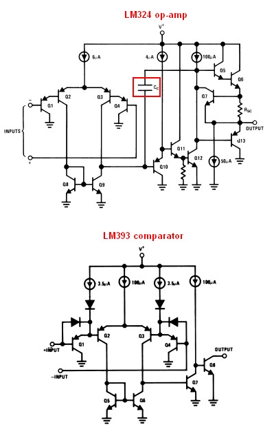 Schematic of LM324 and LM393 showing internal capacitor in the LM324.
2. What is an Op Amp?
An operational amplifier (op amp) is a versatile analog circuit building block known for its high gain and differential inputs. It amplifies the voltage difference between its two inputs, producing an output signal that is a scaled version of this difference. Op amps are widely used in a broad range of applications, including:
- Amplifiers: Increasing the amplitude of signals.
- Filters: Selectively passing or attenuating specific frequency components.
- Oscillators: Generating periodic signals.
- Voltage Regulators: Maintaining a stable output voltage.
- Active Rectifiers: Converting AC signals into DC signals more efficiently than traditional diodes.
Op amps typically employ negative feedback to stabilize their operation and achieve predictable gain characteristics. This feedback mechanism allows for precise control over the amplifier’s behavior, making op amps highly adaptable to various circuit designs.
2.1 Op Amp Applications
Op amps are ubiquitous in analog circuit design, offering a wide range of applications due to their versatility and high performance. Here are several key areas where op amps are used:
- Amplification:
- Inverting Amplifiers: Op amps configured as inverting amplifiers provide voltage gain with a 180-degree phase shift. They are commonly used in audio amplifiers, signal conditioners, and feedback control systems. The gain is determined by the ratio of the feedback resistor to the input resistor, allowing precise control over the amplification factor.
- Non-Inverting Amplifiers: Non-inverting amplifiers provide voltage gain without a phase shift. They are used in applications where preserving the phase of the input signal is crucial. The gain is determined by the ratio of the feedback resistor to the input resistor plus one, offering flexibility in gain selection.
- Differential Amplifiers: Differential amplifiers amplify the difference between two input signals while rejecting common-mode noise. They are used in instrumentation amplifiers, balanced line receivers, and medical devices where high precision and noise immunity are required.
- Filtering:
- Active Low-Pass Filters: Op amps are used to create active low-pass filters that allow signals below a certain cutoff frequency to pass while attenuating signals above the cutoff. These filters are used in audio processing, data acquisition, and anti-aliasing applications to remove unwanted high-frequency components.
- Active High-Pass Filters: Active high-pass filters attenuate signals below a cutoff frequency and allow signals above the cutoff to pass. They are used in audio systems to remove low-frequency noise, in communication systems to block DC components, and in vibration analysis to isolate high-frequency vibrations.
- Band-Pass Filters: Band-pass filters allow signals within a specific frequency range to pass while attenuating signals outside this range. Op amps are used to create active band-pass filters for applications such as audio equalizers, spectrum analyzers, and communication receivers.
- Oscillation:
- Wien Bridge Oscillators: Wien bridge oscillators use an op amp in a positive feedback configuration to generate sinusoidal waveforms. They are used in audio signal generators, function generators, and electronic music synthesizers. The frequency of oscillation is determined by the values of the resistors and capacitors in the Wien bridge network.
- Phase Shift Oscillators: Phase shift oscillators use an op amp and a network of resistors and capacitors to provide a 180-degree phase shift, which is required for oscillation. They are used in low-frequency signal generators, timing circuits, and electronic musical instruments.
- Voltage Regulation:
- Linear Regulators: Op amps are used in linear voltage regulators to maintain a stable output voltage despite variations in input voltage or load current. They compare the output voltage to a reference voltage and adjust the pass transistor to keep the output voltage constant. Linear regulators are used in power supplies, battery chargers, and electronic devices requiring stable voltage sources.
- Instrumentation Amplifiers:
- Sensor Signal Conditioning: Instrumentation amplifiers are specialized op amp circuits designed to amplify low-level signals from sensors while rejecting common-mode noise. They are used in medical devices, industrial sensors, and data acquisition systems where high precision and noise immunity are critical.
- Mathematical Operations:
- Summing Amplifiers: Op amps can be configured as summing amplifiers to add multiple input voltages together. They are used in audio mixers, control systems, and analog computers. The output voltage is proportional to the sum of the input voltages, with each input having its own scaling factor determined by the input resistors.
- Integrators and Differentiators: Op amps can be used to perform integration and differentiation of analog signals. Integrators are used in analog computers, control systems, and waveform shaping circuits. Differentiators are used in edge detectors, high-pass filters, and signal processing applications.
- Active Rectification:
- Precision Rectifiers: Op amps are used to create precision rectifiers that convert AC signals into DC signals with high accuracy. They are used in measurement instruments, signal processing circuits, and power supplies. Unlike traditional diode rectifiers, precision rectifiers can rectify small signals with minimal voltage drop.
- Current Sources and Sinks:
- Controlled Current Supplies: Op amps can be used to create current sources and sinks that provide a constant current to a load. They are used in LED drivers, battery chargers, and precision current control applications. The current is controlled by an external voltage source and a feedback resistor, allowing precise control over the current level.
3. Key Differences Between Comparators and Op Amps
While both comparators and op amps are based on similar underlying amplifier technology, they are designed for different purposes and exhibit distinct characteristics. The primary differences include:
- Functionality: Comparators are designed to compare two voltages and output a binary signal, while op amps are designed for amplification and signal processing.
- Open-Loop Gain: Comparators typically have very high open-loop gain to ensure rapid switching between output states, whereas op amps use negative feedback to control gain and maintain stability.
- Response Time: Comparators are optimized for fast response times to quickly detect voltage differences, while op amps prioritize stability and linearity.
- Output Stage: Comparators often have an open-collector output stage, allowing them to interface with different logic levels, whereas op amps usually have a push-pull output stage for driving various loads.
- Feedback: Op amps rely on negative feedback for stable, linear operation, while comparators operate primarily in open-loop mode without feedback.
- Stability: Op amps are internally compensated to prevent oscillations and ensure stability, while comparators do not have compensation and may oscillate if not properly designed.
3.1 Detailed Comparison Table
| Feature | Comparator | Op Amp |
|---|---|---|
| Function | Voltage Comparison | Amplification and Signal Processing |
| Open-Loop Gain | Very High (for rapid switching) | High (but controlled by feedback) |
| Response Time | Fast | Slower (prioritizes stability) |
| Output Stage | Open-Collector (for logic level interfacing) | Push-Pull (for driving various loads) |
| Feedback | None (operates in open-loop) | Negative Feedback (for stable operation) |
| Stability | No Compensation (may oscillate) | Internally Compensated (prevents oscillations) |
| Input Bias Current | Higher | Lower |
| Voltage Gain | Higher | Lower (Controlled) |
| Slew Rate | Faster | Slower |
| Input Impedance | Lower | Higher |
3.2 Input Bias Current
- Comparators: Comparators generally have higher input bias current compared to op amps. This higher bias current is due to the internal design that optimizes for speed and responsiveness. The higher current allows the comparator to react quickly to changes in the input voltages, which is crucial for its primary function of voltage comparison.
- Op Amps: Op amps, on the other hand, are designed with lower input bias current to minimize the impact on the input signal. This is particularly important in applications where the op amp is used to amplify small signals or in high-impedance circuits. Lower bias current reduces the error introduced by the op amp, ensuring more accurate signal processing.
3.3 Voltage Gain
- Comparators: Comparators are characterized by their very high open-loop voltage gain. This high gain allows even small differences in input voltages to drive the output to its saturation levels quickly, producing a clear digital signal. However, this high gain also means that comparators are not suitable for linear amplification, as they are designed to operate in a binary, on-off state.
- Op Amps: Op amps are designed to provide controlled voltage gain through the use of negative feedback. This feedback stabilizes the amplifier and allows for predictable and linear amplification. The gain of an op amp circuit can be precisely set by selecting appropriate resistor values in the feedback network, making op amps highly versatile for a wide range of amplification tasks.
3.4 Slew Rate
- Comparators: Comparators typically have a faster slew rate compared to op amps. Slew rate is the rate at which the output voltage can change in response to a change in the input voltage. A faster slew rate allows comparators to switch quickly between their high and low output states, which is essential for high-speed voltage comparison applications.
- Op Amps: Op amps generally have a slower slew rate compared to comparators. While a high slew rate is desirable, op amps prioritize stability and linearity. The slew rate is often limited by the internal compensation circuitry, which prevents oscillations and ensures stable operation.
3.5 Input Impedance
- Comparators: Comparators tend to have lower input impedance compared to op amps. The lower input impedance can affect the accuracy of the comparison if the input signal source has a high output impedance. In such cases, buffering the input signal may be necessary to ensure accurate comparison.
- Op Amps: Op amps are designed with high input impedance to minimize the loading effect on the input signal source. This high impedance ensures that the op amp does not significantly alter the input signal, making it suitable for a wide range of applications, including those with sensitive or high-impedance signal sources.
4. Can a Comparator Be Used as an Op Amp?
While a comparator and an op amp share a similar internal structure, using a comparator as an op amp is generally not recommended. Comparators lack the internal compensation found in op amps, making them prone to oscillations when used in linear amplification circuits. Additionally, the open-loop configuration of comparators, optimized for high-speed switching, makes them unsuitable for applications requiring stable, controlled gain.
4.1 Limitations of Using a Comparator as an Op Amp
Using a comparator as an op amp comes with several limitations:
- Stability Issues: Comparators are not internally compensated for stability, which means they are highly susceptible to oscillations when used in circuits with negative feedback. Op amps, on the other hand, are designed with internal compensation to ensure stable operation in a variety of feedback configurations.
- Lack of Linearity: Comparators are designed to operate in a binary, on-off state and are not optimized for linear amplification. Their high open-loop gain and lack of feedback control make them unsuitable for applications requiring precise, linear amplification.
- Poor Performance in Linear Applications: Comparators typically have higher input bias currents and offset voltages compared to op amps, which can degrade their performance in linear applications. These parameters can introduce errors and inaccuracies in the amplified signal.
- Limited Bandwidth: Comparators often have a limited bandwidth compared to op amps, which can restrict their use in high-frequency applications. The high gain and fast switching speeds of comparators come at the expense of bandwidth, making them less suitable for amplifying high-frequency signals.
- Output Characteristics: Comparators often have an open-collector output, which requires a pull-up resistor to provide a defined high state. This is different from the push-pull output of op amps, which can source and sink current, making them more versatile for driving various loads.
- Unpredictable Behavior: Without proper compensation and feedback control, the behavior of a comparator in a linear circuit can be unpredictable and difficult to manage. This can lead to unreliable performance and make it challenging to design stable and accurate circuits.
4.2 Scenarios Where It Might Be Considered
Despite the limitations, there might be specific scenarios where using a comparator as an op amp could be considered:
- Simple Switching Applications: In very basic switching applications where precise linear amplification is not required, a comparator might be used as a rudimentary amplifier. However, this is generally not recommended due to the potential for instability and poor performance.
- Educational Purposes: For educational purposes, using a comparator as an op amp can be a useful exercise to understand the differences between the two components and the importance of feedback and compensation in amplifier circuits.
- Limited Component Availability: In situations where an op amp is not readily available, and a simple amplification task needs to be performed, a comparator might be used as a temporary solution. However, this should be done with caution and with a clear understanding of the potential limitations.
- Specialized Circuits: In some specialized circuits, such as certain types of oscillators or non-linear signal processors, the unique characteristics of a comparator might be exploited for specific design purposes. However, these applications are rare and require careful design and analysis.
In summary, while it is technically possible to use a comparator as an op amp in certain limited scenarios, it is generally not recommended due to the potential for instability, poor linearity, and other performance limitations. Op amps are specifically designed for amplification and signal processing, and their internal compensation and feedback control make them much more suitable for these applications.
5. Can an Op Amp Be Used as a Comparator?
Yes, an op amp can be used as a comparator, but with certain caveats. When used as a comparator, the op amp operates in an open-loop configuration, maximizing its gain to quickly switch between output states. However, this can lead to slower response times and potential instability compared to dedicated comparators.
5.1 Advantages of Using an Op Amp as a Comparator
- Availability: Op amps are more commonly available and widely used than comparators, making them a convenient choice if a dedicated comparator is not on hand.
- Versatility: Op amps can be used for both amplification and comparison, providing flexibility in circuit design and reducing the number of different components needed in a project.
- Cost-Effectiveness: In some cases, using an op amp as a comparator can be more cost-effective, especially if the same op amp is already being used for other functions in the circuit.
- Familiarity: Many engineers and hobbyists are more familiar with op amps than comparators, making it easier to design and troubleshoot circuits using op amps for both amplification and comparison.
5.2 Disadvantages of Using an Op Amp as a Comparator
- Slower Response Time: Op amps are not optimized for fast switching speeds, so they typically have a slower response time compared to dedicated comparators. This can be a significant limitation in high-speed applications where rapid voltage comparisons are required.
- Instability: Op amps are designed to operate with negative feedback, and when used as a comparator in an open-loop configuration, they can be prone to oscillations and instability. This can lead to unreliable performance and make it difficult to achieve a clean, stable output signal.
- Lack of Hysteresis: Op amps do not have built-in hysteresis, which is a feature that helps to prevent oscillations and noise-induced switching in comparators. Without hysteresis, the output of an op amp used as a comparator can switch rapidly and erratically when the input voltage is near the threshold.
- Output Voltage Swing: Op amps typically have a limited output voltage swing compared to dedicated comparators. This can restrict their use in applications where a wide output voltage range is required.
- Input Protection: Op amps may not have the same input protection features as comparators, making them more susceptible to damage from overvoltage or electrostatic discharge (ESD).
5.3 Techniques to Improve Performance
To mitigate the disadvantages of using an op amp as a comparator, several techniques can be employed:
- Adding Hysteresis: Hysteresis can be added to the op amp circuit by using positive feedback. This creates a Schmitt trigger configuration, which helps to prevent oscillations and noise-induced switching. The hysteresis provides a deadband around the threshold voltage, ensuring that the output switches cleanly and reliably.
- Using a Faster Op Amp: Selecting an op amp with a higher slew rate and bandwidth can improve the response time and reduce the risk of oscillations. However, it is important to ensure that the op amp is still stable in the open-loop configuration.
- Adding a Pull-Up Resistor: If the op amp has an open-collector output, a pull-up resistor can be added to the output to provide a defined high state. This ensures that the output signal is compatible with other logic circuits.
- Filtering the Input Signal: Filtering the input signal can reduce noise and prevent false triggering. A low-pass filter can be used to attenuate high-frequency noise, while a band-pass filter can be used to isolate the desired signal.
- Proper Power Supply Decoupling: Ensuring proper power supply decoupling can reduce noise and improve stability. Decoupling capacitors should be placed close to the op amp’s power supply pins to provide a low-impedance path for high-frequency currents.
5.4 Example Circuit: Op Amp as Comparator with Hysteresis
A common way to use an op amp as a comparator is to add hysteresis using positive feedback. Here’s an example circuit:
- Components:
- Op Amp (e.g., LM741, LM358)
- Two Resistors (R1 and R2)
- Input Voltage (Vin)
- Reference Voltage (Vref)
- Circuit Configuration:
- Connect the inverting input of the op amp to the reference voltage (Vref).
- Connect the input voltage (Vin) to one end of resistor R1.
- Connect the other end of R1 to the non-inverting input of the op amp.
- Connect resistor R2 between the output of the op amp and the non-inverting input.
This configuration creates positive feedback, which introduces hysteresis. The switching thresholds are determined by the values of R1 and R2.
5.5 How Hysteresis Works
Hysteresis adds two different threshold voltages, an upper threshold (V+) and a lower threshold (V-). The output will switch high when the input voltage exceeds V+ and switch low when the input voltage falls below V-. This deadband prevents rapid switching caused by noise.
Formulas for Threshold Voltages:
- *V+ = Vref + (R1 / (R1 + R2)) (Vout_high – Vref)**
- *V- = Vref + (R1 / (R1 + R2)) (Vout_low – Vref)**
Where:
- Vout_high: The high output voltage of the op amp.
- Vout_low: The low output voltage of the op amp.
5.6 Choosing Resistor Values
The resistor values for R1 and R2 determine the amount of hysteresis. A larger R2 relative to R1 results in more hysteresis. Here’s a step-by-step guide to choosing appropriate resistor values:
-
Determine the Desired Hysteresis (ΔV): Decide on the voltage difference between the upper and lower thresholds. This depends on the expected noise level and the sensitivity required for the application.
-
Choose a Convenient Value for R1: Start with a standard resistor value for R1, such as 1 kΩ to 10 kΩ.
-
Calculate R2: Use the following formula to calculate R2:
*R2 = R1 ((Vout_high – Vout_low) / ΔV – 1)**
-
Select Standard Resistor Value: Choose a standard resistor value for R2 that is close to the calculated value. You may need to adjust R1 slightly to achieve the desired hysteresis exactly.
5.7 Example Calculation
Let’s assume we want to design a comparator with:
- Vref = 2.5V
- Vout_high = 5V
- Vout_low = 0V
- ΔV = 0.2V (desired hysteresis)
- R1 = 1 kΩ (chosen value)
Using the formula:
R2 = 1 kΩ ((5V – 0V) / 0.2V – 1) = 1 kΩ (25 – 1) = 24 kΩ
A standard resistor value close to 24 kΩ is 24 kΩ. So, we can use R1 = 1 kΩ and R2 = 24 kΩ.
Using these values, we can calculate the threshold voltages:
- V+ = 2.5V + (1 kΩ / (1 kΩ + 24 kΩ)) (5V – 2.5V) = 2.5V + (1 / 25) 2.5V = 2.5V + 0.1V = 2.6V
- V- = 2.5V + (1 kΩ / (1 kΩ + 24 kΩ)) (0V – 2.5V) = 2.5V + (1 / 25) (-2.5V) = 2.5V – 0.1V = 2.4V
Thus, the upper threshold is 2.6V, and the lower threshold is 2.4V, providing a hysteresis of 0.2V.
5.8 Practical Considerations
- Power Supply: Ensure that the power supply voltages are stable and within the op amp’s specifications.
- Component Tolerances: Resistor tolerances can affect the accuracy of the hysteresis. Use precision resistors if high accuracy is required.
- Op Amp Selection: Choose an op amp with appropriate input bias current, input offset voltage, and slew rate for the application.
- Layout: Proper PCB layout techniques, such as minimizing trace lengths and using ground planes, can help to reduce noise and improve stability.
5.9 Conclusion
Using an op amp as a comparator can be a practical solution when a dedicated comparator is not available. However, it is essential to understand the limitations and take steps to mitigate them. Adding hysteresis is a simple and effective way to improve the performance and stability of an op amp comparator. By carefully selecting components and following good design practices, you can create a reliable comparator circuit using an op amp.
5.10 Alternative Solutions
- Dedicated Comparators: Use dedicated comparators like the LM393 or LM311 for better performance and stability.
- Comparator ICs with Hysteresis: Choose comparator ICs with built-in hysteresis for ease of design and improved noise immunity.
6. Common Mistakes to Avoid
When working with comparators and op amps, several common mistakes can lead to suboptimal performance or circuit malfunction. Avoiding these pitfalls can save time and improve the reliability of your designs:
- Ignoring Stability Issues:
- Mistake: Failing to consider stability issues when using an op amp as a comparator or when designing comparator circuits without proper feedback.
- Solution: Always analyze the stability of your circuit and add hysteresis or compensation as needed to prevent oscillations and ensure reliable performance.
- Overlooking Input Bias Current:
- Mistake: Neglecting the effects of input bias current, especially when using high-impedance input sources.
- Solution: Choose components with low input bias current or use compensation techniques to minimize the impact on your circuit’s accuracy.
- Improper Power Supply Decoupling:
- Mistake: Not providing adequate power supply decoupling, leading to noise and instability.
- Solution: Use decoupling capacitors close to the power supply pins of your comparators and op amps to provide a stable and clean power source.
- Failing to Consider Response Time:
- Mistake: Ignoring the response time of comparators and op amps, especially in high-speed applications.
- Solution: Select components with appropriate response times for your application and consider the effects of propagation delay on your circuit’s performance.
- Incorrect Grounding:
- Mistake: Implementing improper grounding techniques, leading to ground loops and noise.
- Solution: Use a solid ground plane and star grounding techniques to minimize noise and ensure a stable reference point for your circuit.
- Exceeding Input Voltage Limits:
- Mistake: Applying input voltages beyond the specified limits of your comparators and op amps, potentially damaging the components.
- Solution: Always ensure that input voltages are within the allowable range and use input protection circuitry if necessary.
- Ignoring Output Loading:
- Mistake: Overlooking the effects of output loading on the performance of your comparators and op amps.
- Solution: Consider the load impedance and choose components with appropriate output drive capabilities. Use buffer amplifiers if needed to isolate the output from heavy loads.
- Using Incorrect Feedback Configuration:
- Mistake: Implementing incorrect feedback configurations, leading to instability or unwanted behavior.
- Solution: Carefully design your feedback network and verify its stability using simulation tools or mathematical analysis.
- Neglecting Temperature Effects:
- Mistake: Failing to account for temperature effects on component parameters, such as input offset voltage and bias current.
- Solution: Choose components with low temperature coefficients and consider using temperature compensation techniques in critical applications.
- Skipping Simulation and Testing:
- Mistake: Bypassing simulation and testing, leading to unforeseen issues in the final design.
- Solution: Always simulate your circuits before building them and thoroughly test the final design to ensure it meets your requirements.
By being aware of these common mistakes and taking steps to avoid them, you can improve the performance and reliability of your comparator and op amp circuits.
7. Conclusion
In summary, while comparators and op amps share a similar foundational technology, they are optimized for different purposes. Comparators excel at fast voltage comparisons, while op amps are designed for versatile amplification and signal processing. Though an op amp can function as a comparator and vice versa, it’s essential to understand the trade-offs and potential limitations. Using the right component for the right application ensures optimal performance and reliability in electronic circuit designs. For more detailed comparisons and resources to help you make informed decisions, visit COMPARE.EDU.VN today.
Choosing the right component for your specific application can be challenging. At COMPARE.EDU.VN, we provide comprehensive comparisons and detailed analyses to help you make informed decisions. Whether you’re deciding between a comparator and an op amp, or evaluating different models within each category, our resources are designed to simplify the selection process. Visit COMPARE.EDU.VN today to explore detailed comparisons, user reviews, and expert insights. Make your decision with confidence using COMPARE.EDU.VN.
Need help deciding which component is best for your project? Visit COMPARE.EDU.VN for in-depth comparisons and expert advice. Our detailed analyses cover a wide range of products and services, helping you make informed decisions.
Contact Us:
Address: 333 Comparison Plaza, Choice City, CA 90210, United States
WhatsApp: +1 (626) 555-9090
Website: compare.edu.vn
8. Frequently Asked Questions (FAQ)
-
Can I use any op amp as a comparator?
- While technically possible, not all op amps are suitable for use as comparators. Op amps lacking internal compensation may oscillate when used in an open-loop configuration. It is recommended to choose an op amp with a high slew rate and add hysteresis to improve stability.
-
What is hysteresis, and why is it important in comparators?
- Hysteresis is a technique used to prevent oscillations and noise-induced switching in comparators. It introduces two different threshold voltages, an upper threshold (V+) and a lower threshold (V-), creating a deadband that ensures the output switches cleanly and reliably.
-
What is the difference between a comparator and an op amp?
- Comparators are designed to compare two voltages and output a binary signal, while op amps are designed for amplification and signal processing. Comparators have very high open-loop gain and fast response times, while op amps use negative feedback to control gain and maintain stability.
-
Why does a comparator have a faster response time than an op amp?
- Comparators are optimized for fast switching speeds, allowing them to quickly detect voltage differences. Op amps, on the other hand, prioritize stability and linearity, which results in a slower response time.
-
What is an open-collector output, and why is it used in comparators?
- An open-collector output is a type of output that requires a pull-up resistor to provide a defined high state. It is used in comparators to allow them to interface with different logic levels and drive various loads.
-
How do I add hysteresis to an op amp circuit when using it as a comparator?
- Hysteresis can be added to an op amp circuit by using positive feedback. This creates a Schmitt trigger configuration, which helps to prevent oscillations and noise-induced switching.
-
What are some common applications of comparators?
- Comparators are used in various applications, including analog-to-digital converters (ADCs), threshold detectors, zero-crossing detectors, and relaxation oscillators.
-
What are some common applications of op amps?
- Op amps are used in a broad range of applications, including amplifiers, filters, oscillators, voltage regulators, and active rectifiers.
-
How do I choose the right resistor values when adding hysteresis to an op amp comparator circuit?
- The resistor values for R1 and R2 determine the amount of hysteresis. A larger R2 relative to R1 results in more hysteresis. Choose a convenient value for R1, then calculate R2 using the formula: R2 = R1 * ((Vout_high – Vout_low) / ΔV – 1).
-
What are some common mistakes to avoid when working with comparators and op amps?
- Common mistakes include ignoring stability issues, overlooking input bias current, improper power supply decoupling, failing to consider response time, and incorrect grounding.