Yes, the ATtiny85 microcontroller incorporates an internal analog comparator that can be configured to trigger interrupts. COMPARE.EDU.VN helps you understand its capabilities and shows how to leverage this feature for your embedded projects. Utilizing the internal comparator offers a cost-effective and efficient method for analog signal comparison, leading to optimized system responses.
Table of Contents
1. Understanding the ATtiny85 Analog Comparator
2. Key Registers for Configuring the Analog Comparator
3. Using AIN1 as Negative Input
4. Using ADC1 as Negative Input
5. Configuring the Analog Comparator with AIN0 and AIN1 Inputs
6. Sample Code: AIN0 and AIN1 as Inputs
7. Configuring Analog Comparator Using AIN0, ADC1 as Inputs
8. Sample Code AIN0 and ADC1 as Inputs
9. Optimizing ATtiny85 Projects with COMPARE.EDU.VN
10. Frequently Asked Questions (FAQs)
1. Understanding the ATtiny85 Analog Comparator
The ATtiny85 features an integrated analog comparator, a valuable tool for comparing two analog input signals and generating a digital output based on the comparison. This eliminates the need for external comparator chips in many applications, saving board space and reducing cost. Instead of relying on external components, the ATtiny85’s built-in comparator offers a streamlined approach to analog signal processing.
The analog comparator in the ATtiny85 can be configured to trigger interrupts, allowing the microcontroller to respond immediately to changes in the analog signals. This is useful in applications that require real-time monitoring and control. The comparator’s positive input is connected to the AIN0 (PB0) pin, while the negative input can be chosen from AIN1 (PB1) or any of the ADC input channels (ADC0, ADC1, ADC2, ADC3), offering versatility in signal selection.
The ATtiny85’s analog comparator operates independently of the ADC, providing continuous monitoring of analog signals. The comparator can trigger interrupts on rising, falling, or toggling edges of the comparator output, enabling versatile event detection. This is essential for creating responsive and efficient embedded systems.
2. Key Registers for Configuring the Analog Comparator
Several registers are essential for configuring the ATtiny85’s analog comparator:
-
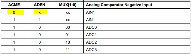
ADCSRB (ADC Control and Status Register B): This register includes the ACME (Analog Comparator Multiplexer Enable) bit, which selects the negative input to the comparator. When ACME is 0, AIN1 is used as the negative input. When ACME is 1 and the ADC is disabled (ADEN = 0), ADC input channels can be used.
-
ADCSRA (ADC Control and Status Register A): The ADEN bit in this register enables or disables the ADC. Disabling the ADC allows the ADC channels (ADC0, ADC1, ADC2, ADC3) to be used as negative inputs to the comparator.
-
ADMUX (ADC Multiplexer Selection Register): After disabling ADEN and enabling ACME, the MUX1 and MUX0 bits in this register select the specific ADC channel to use as the negative input.
-
ACSR (Analog Comparator Control and Status Register): This register controls various comparator functions:
- Bit 7 (ACD) turns the comparator on or off. Setting ACD disables the comparator, saving power.
- Bit 6 (ACBG) selects the bandgap reference voltage (typically 1.1V) as the positive input to the comparator.
- Bit 5 (ACO) is the output bit that provides the digital output of the comparator.
- Bit 4 (ACI) is the flag register that is set when the comparator output meets the criteria set by ACIS1 and ACIS0 bits.
- Bit 3 (ACIE) is the interrupt enable bit that enables interrupts to be triggered when the ACI flag is set.
- Bits 1 and 0 (ACIS1, ACIS0) determine the criteria for triggering interrupts, as shown in the table below:
| ACIS1 | ACIS0 | Description |
|---|---|---|
| 0 | 0 | Interrupt on comparator output change. |
| 0 | 1 | Reserved. |
| 1 | 0 | Interrupt on falling edge of comparator output. |
| 1 | 1 | Interrupt on rising edge of comparator output. |
Understanding these registers is crucial for configuring the analog comparator to meet specific application requirements.
3. Using AIN1 as Negative Input
To use AIN1 (PB1) as the negative input to the comparator, the ACME bit in the ADCSRB register must be cleared (set to 0). This disables the ADC multiplexer and directly connects AIN1 to the negative input of the comparator.
Here’s a summary of the steps:
- Set ACME to 0 in the ADCSRB register.
- Ensure the ADC is disabled by setting ADEN to 0 in the ADCSRA register (though not strictly necessary when ACME is 0).
- Read the ACO bit in the ACSR register to determine the comparator output.
Using AIN1 as the negative input is straightforward and suitable for simple comparison tasks.
4. Using ADC1 as Negative Input
To use an ADC channel, such as ADC1, as the negative input, you need to enable the ADC multiplexer and select the desired channel. Here’s how:
- Set ACME to 1 in the ADCSRB register to enable the ADC multiplexer.
- Disable the ADC by setting ADEN to 0 in the ADCSRA register.
- Select the ADC channel by setting the MUX1 and MUX0 bits in the ADMUX register. For ADC1, set MUX1 to 0 and MUX0 to 1.
The table below shows the MUX1 and MUX0 bit settings for selecting different ADC channels:
| MUX1 | MUX0 | ADC Channel Selected |
|---|---|---|
| 0 | 0 | ADC0 |
| 0 | 1 | ADC1 |
| 1 | 0 | ADC2 |
| 1 | 1 | ADC3 |
Once the ADC channel is selected, you can read the ACO bit in the ACSR register to get the comparator output. This setup allows you to compare the voltage on AIN0 with the voltage on any of the ADC input channels, offering flexibility in analog signal comparison.
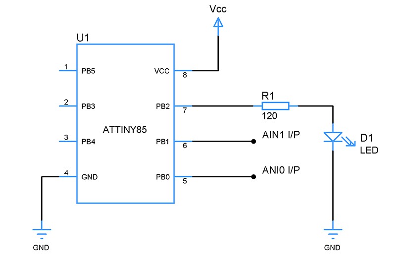
5. Configuring the Analog Comparator with AIN0 and AIN1 Inputs
To configure the analog comparator using AIN0 and AIN1 as inputs, follow these steps:
- Write 0 to the ACME bit in the ADCSRB register to disable the ADC multiplexer.
- Read the ACO analog comparator output bit in the ACSR register to determine the comparator output.
The following circuit diagram illustrates the configuration with PB1 and PB0 as negative and positive inputs:
In this circuit, a LED connected to PB2 indicates the status of the comparator output.
6. Sample Code: AIN0 and AIN1 as Inputs
Here’s a sample code snippet to configure the analog comparator with AIN0 and AIN1 as inputs:
#include <avr/io.h>
#include <util/delay.h>

#define F_CPU 16000000UL

void comp_setup() {
    DDRB |= (1 << PB2); // Set PB2 as output
    ACSR = (0 << ACD) | // Enable comparator
           (0 << ACBG) | // Disable bandgap
           (0 << ACI) |  // Clear interrupt flag
           (0 << ACIE) | // Disable interrupt
           (0 << ACIS1) | (0 << ACIS0); // Trigger on output change
    ADCSRB &= ~(1 << ACME); // Disable ADC multiplexer
}

int main(void) {
    comp_setup();

    while (1) {
        if (ACSR & (1 << ACO)) {
            PORTB |= (1 << PB2); // LED on
        } else {
            PORTB &= ~(1 << PB2); // LED off
        }
        _delay_ms(100);
    }

    return 0;
}
This code sets up the comparator to compare the voltages on AIN0 and AIN1 and toggles an LED based on the comparison result.
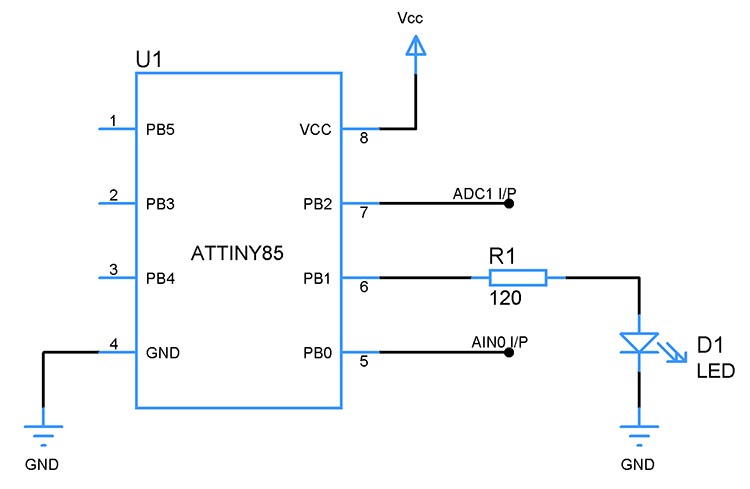
7. Configuring Analog Comparator Using AIN0, ADC1 as Inputs
To configure the analog comparator with AIN0 as the positive input and ADC1 as the negative input:
- Select ADC1 as the non-inverting input by writing 1 to the ACME bit in the ADCSRB register and writing 01 to the MUX1, MUX0 bits in the ADMUX register.
- Disable the ADC by writing 0 to the ADEN bit in the ADCSRA register.
- Read the Analog comparator output bit ACO to determine the comparator output.
8. Sample Code AIN0 and ADC1 as Inputs
#include <avr/io.h>
#include <util/delay.h>

#define F_CPU 16000000UL

void comp_setup() {
    DDRB |= (1 << PB2); // Set PB2 as output
    ACSR = (0 << ACD) | // Enable comparator
           (0 << ACBG) | // Disable bandgap
           (0 << ACI) |  // Clear interrupt flag
           (0 << ACIE) | // Disable interrupt
           (0 << ACIS1) | (0 << ACIS0); // Trigger on output change

    ADCSRB |= (1 << ACME); // Enable ADC multiplexer
    ADCSRA &= ~(1 << ADEN); // Disable ADC

    ADMUX = (0 << MUX1) | (1 << MUX0); // Select ADC1
}

int main(void) {
    comp_setup();

    while (1) {
        if (ACSR & (1 << ACO)) {
            PORTB |= (1 << PB2); // LED on
        } else {
            PORTB &= ~(1 << PB2); // LED off
        }
        _delay_ms(100);
    }

    return 0;
}
This code configures the ATtiny85 to use ADC1 as the negative input to the comparator and toggles an LED based on the comparison result.
9. Optimizing ATtiny85 Projects with COMPARE.EDU.VN
At COMPARE.EDU.VN, we understand the challenges of selecting the right components and configurations for your projects. Our platform offers comprehensive comparisons and insights to help you make informed decisions.
Benefits of using COMPARE.EDU.VN:
- Detailed Comparisons: Access in-depth comparisons of microcontrollers, sensors, and other electronic components.
- Expert Reviews: Read reviews and analysis from industry experts to understand the strengths and weaknesses of different options.
- Community Insights: Benefit from the experiences and knowledge shared by other developers in our community.
- Up-to-Date Information: Stay informed with the latest specifications, datasheets, and pricing information.
Whether you’re comparing microcontrollers, sensors, or software tools, COMPARE.EDU.VN provides the resources you need to optimize your projects. Explore our site today to discover how we can help you make the best choices for your specific requirements.
Ready to take your projects to the next level? Visit COMPARE.EDU.VN to find detailed comparisons and make informed decisions.
- Address: 333 Comparison Plaza, Choice City, CA 90210, United States
- WhatsApp: +1 (626) 555-9090
- Website: COMPARE.EDU.VN
10. Frequently Asked Questions (FAQs)
-
Can the ATtiny85 analog comparator trigger interrupts?
Yes, the ATtiny85 analog comparator can be configured to trigger interrupts, allowing the microcontroller to respond immediately to changes in the analog signals.
-
What are the input options for the ATtiny85 analog comparator?
The positive input is AIN0 (PB0), and the negative input can be either AIN1 (PB1) or any of the ADC input channels (ADC0, ADC1, ADC2, ADC3).
-
How do I select AIN1 as the negative input?
Clear the ACME bit (set to 0) in the ADCSRB register to disable the ADC multiplexer and use AIN1 as the negative input.
-
How do I use an ADC channel as the negative input?
Set the ACME bit to 1 in the ADCSRB register, disable the ADC by setting ADEN to 0 in the ADCSRA register, and select the desired ADC channel using the MUX1 and MUX0 bits in the ADMUX register.
-
What is the purpose of the ACSR register?
The ACSR (Analog Comparator Control and Status Register) controls various comparator functions, including enabling/disabling the comparator, selecting the bandgap reference voltage, and setting interrupt trigger criteria.
-
How do I enable interrupts for the analog comparator?
Set the ACIE bit (Analog Comparator Interrupt Enable) in the ACSR register to enable interrupts.
-
How do I configure the interrupt trigger criteria?
Use the ACIS1 and ACIS0 bits in the ACSR register to select the interrupt trigger condition (e.g., rising edge, falling edge, or output change).
-
Can the analog comparator operate independently of the ADC?
Yes, the analog comparator can operate independently of the ADC, providing continuous monitoring of analog signals.
-
What is the typical bandgap reference voltage for the ATtiny85?
The typical bandgap reference voltage is 1.1V.
-
Where can I find more resources and comparisons for optimizing my ATtiny85 projects?
Visit COMPARE.EDU.VN for detailed comparisons, expert reviews, and community insights to help you make informed decisions.
By understanding and utilizing the ATtiny85’s internal analog comparator, developers can create efficient and responsive embedded systems. With resources like compare.edu.vn, optimizing your projects becomes more straightforward and effective.