A Triac And Scr Are Compared Mcqs to understand their differences. COMPARE.EDU.VN offers a detailed comparison, helping you choose the right component for your needs. Explore the contrasts in functionality and applications to make informed decisions, and enhance your understanding of electronic components with a comprehensive comparison of semiconductors and switching devices.
1. What Is an SCR (Silicon Controlled Rectifier)?
An SCR, or Silicon Controlled Rectifier, is a four-layer, three-terminal semiconductor device used for controlling high power. The SCR is primarily utilized in applications requiring unidirectional current flow control and serves as a cornerstone in power electronics. Let’s delve deeper into understanding its key points.
1.1 Key Features of SCRs
SCRs are known for their specific attributes:
- Unidirectional Conduction: SCRs conduct current in only one direction, making them suitable for AC rectification.
- Three Terminals: They have an anode, cathode, and gate.
- Triggering Mechanism: A positive current pulse at the gate triggers the SCR into conduction.
- Latching Behavior: Once triggered, the SCR remains in the conducting state until the current through it falls below a certain holding current.
- High Power Handling: SCRs can handle substantial amounts of current and voltage.
- Applications: Commonly used in rectifiers, inverters, and phase control circuits.
1.2 Working Principle of SCRs
The SCR operates in three states: forward blocking, forward conduction, and reverse blocking. In the forward blocking state, the SCR doesn’t conduct until a gate signal is applied. Once triggered, it enters the forward conduction state and continues to conduct until the current drops below the holding current. In the reverse blocking state, the SCR blocks current regardless of the gate signal.
1.3 Advantages and Disadvantages of SCRs
SCRs offer several advantages:
- High Efficiency: Efficient control of large power.
- Reliability: Robust and long-lasting.
- Simple Control Circuitry: Requires only a small gate current to trigger.
However, there are also disadvantages:
- Unidirectional: Can only control current in one direction.
- Difficult to Turn Off: Requires special techniques to stop conduction once triggered.
- Limited Frequency Response: Not suitable for high-frequency applications.
2. What Is a TRIAC (Triode for Alternating Current)?
A TRIAC, short for Triode for Alternating Current, is a three-terminal semiconductor device used for controlling AC power. The TRIAC can control current flow in both directions, making it suitable for AC applications. Here’s an exploration of its key aspects.
2.1 Key Features of TRIACs
TRIACs are characterized by the following:
- Bidirectional Conduction: TRIACs can conduct current in both directions.
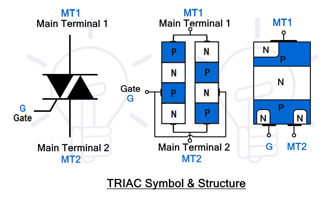
- Three Terminals: They have two main terminals (MT1 and MT2) and a gate terminal.
- Triggering Mechanism: A positive or negative current pulse at the gate can trigger the TRIAC into conduction.
- Applications: Commonly used in light dimmers, motor speed controls, and AC switches.
- Symmetrical Switching: Offers relatively symmetrical switching characteristics.
2.2 Working Principle of TRIACs
The TRIAC functions by allowing current to flow between its main terminals when triggered by a gate signal. This triggering can occur regardless of the polarity of the voltage applied across the main terminals. Once triggered, the TRIAC continues to conduct until the current drops below the holding current.
2.3 Advantages and Disadvantages of TRIACs
TRIACs offer distinct advantages:
- Bidirectional Control: Ability to control AC power directly.
- Simple Circuitry: Requires fewer components compared to using two SCRs for AC control.
- Versatility: Suitable for a wide range of AC power control applications.
However, TRIACs also have drawbacks:
- Lower Power Handling Compared to SCRs: Generally, TRIACs handle less power than SCRs.
- Non-Symmetrical Triggering: Triggering characteristics can vary slightly depending on the polarity of the gate signal.
- Higher Leakage Current: Can have higher leakage current compared to SCRs.
3. A Triac And Scr Are Compared Mcq: What Are The Primary Differences?
The primary differences between a TRIAC and an SCR revolve around their conduction capabilities, control mechanisms, and applications. Understanding these distinctions is crucial for selecting the appropriate device for a specific application.
3.1 Conduction Characteristics
- SCR: Unidirectional, allowing current flow in only one direction.
- TRIAC: Bidirectional, allowing current flow in both directions.
3.2 Control Mechanism
- SCR: Triggered by a positive gate current and requires the current to drop below the holding current to turn off.
- TRIAC: Triggered by either a positive or negative gate current and also requires the current to drop below the holding current to turn off.
3.3 Application Areas
- SCR: Used in applications requiring unidirectional current control, such as rectifiers and high-power DC control.
- TRIAC: Used in AC power control applications, such as light dimmers, motor speed controls, and AC switches.
3.4 Detailed Comparison Table: A Triac And Scr Are Compared Mcq
| Feature | SCR (Silicon Controlled Rectifier) | TRIAC (Triode for Alternating Current) |
|---|---|---|
| Conduction | Unidirectional | Bidirectional |
| Number of Terminals | 3 (Anode, Cathode, Gate) | 3 (MT1, MT2, Gate) |
| Gate Triggering | Positive Current Pulse | Positive or Negative Current Pulse |
| Control Type | Unidirectional Control | Bidirectional Control |
| Power Handling | High | Moderate |
| Symmetrical Switching | N/A | Relatively Symmetrical |
| Typical Applications | Rectifiers, DC Power Control | Light Dimmers, AC Motor Control |

4. Key Parameters to Consider When Selecting Between TRIAC and SCR
Selecting between a TRIAC and an SCR involves considering several parameters to ensure the chosen device meets the application’s requirements.
4.1 Voltage and Current Ratings
- Voltage Rating: Ensure the device’s voltage rating is sufficient for the maximum voltage in the circuit.
- Current Rating: Select a device with a current rating that exceeds the maximum expected current in the application.
4.2 Triggering Requirements
- Gate Trigger Current: Consider the gate trigger current required to switch the device on.
- Gate Trigger Voltage: Evaluate the gate trigger voltage needed for reliable switching.
4.3 Switching Speed
- Turn-On Time: Evaluate the time it takes for the device to switch on.
- Turn-Off Time: Assess the time it takes for the device to switch off.
4.4 Thermal Considerations
- Operating Temperature: Ensure the device’s operating temperature range is suitable for the application environment.
- Heat Dissipation: Consider the device’s heat dissipation capabilities and the need for heat sinking.
4.5 Application-Specific Requirements
- Frequency: Consider the frequency of the AC signal being controlled.
- Load Type: Evaluate the type of load being controlled (e.g., inductive, capacitive, resistive).
5. Practical Applications of SCRs
SCRs find extensive use in applications requiring unidirectional current control and high power handling.
5.1 Rectifiers
SCRs are commonly used in rectifiers to convert AC to DC. Their ability to control the conduction angle allows for efficient voltage regulation.
5.2 DC Motor Control
SCRs are employed in DC motor control circuits, enabling precise speed and torque control.
5.3 Inverters
In high-power inverters, SCRs convert DC to AC, playing a crucial role in renewable energy systems and uninterruptible power supplies (UPS).
5.4 Overvoltage Protection
SCRs are utilized in overvoltage protection circuits to quickly clamp voltage spikes, protecting sensitive electronic components.
6. Practical Applications of TRIACs
TRIACs are widely used in applications requiring bidirectional AC power control, offering versatility and ease of implementation.
6.1 Light Dimmers
TRIACs are extensively used in light dimmers to control the intensity of incandescent and LED lamps.
6.2 AC Motor Speed Control
In AC motor speed control circuits, TRIACs regulate the voltage applied to the motor, adjusting its speed.
6.3 Solid-State Relays (SSRs)
TRIACs are integral components of SSRs, providing reliable and fast switching of AC loads.
6.4 AC Power Switches
TRIACs function as AC power switches in various appliances and industrial equipment, offering efficient control of AC circuits.
7. Circuit Designs and Examples: A Triac And Scr Are Compared Mcq
Designing circuits with SCRs and TRIACs requires careful consideration of the device characteristics and the application requirements.
7.1 SCR Phase Control Circuit
In a phase control circuit, an SCR is triggered at a specific angle of the AC waveform, controlling the average voltage applied to the load.
Components Required:
- AC voltage source
- SCR
- Load (e.g., resistive load)
- Gate triggering circuit (e.g., DIAC and resistor)
Circuit Operation:
- The AC voltage is applied to the SCR and the load.
- The gate triggering circuit generates a pulse at a specific phase angle.
- The SCR is triggered, allowing current to flow through the load for the remainder of the AC cycle.
- The conduction angle can be adjusted by varying the timing of the gate pulse, thereby controlling the power delivered to the load.
7.2 TRIAC Light Dimmer Circuit
A TRIAC light dimmer circuit uses a TRIAC to control the AC voltage applied to a light bulb, adjusting its brightness.
Components Required:
- AC voltage source
- TRIAC
- Light bulb
- DIAC
- Variable resistor and capacitor
Circuit Operation:
- The AC voltage is applied to the TRIAC and the light bulb.
- The variable resistor and capacitor form an RC timing circuit that controls the firing angle of the DIAC.
- When the voltage across the capacitor reaches the breakover voltage of the DIAC, the DIAC conducts, triggering the TRIAC.
- The TRIAC allows current to flow through the light bulb for the remainder of the AC cycle.
- Adjusting the variable resistor changes the charging time of the capacitor, thereby varying the firing angle and the brightness of the light bulb.
8. Advanced Techniques for Enhancing SCR and TRIAC Performance
Improving the performance of SCR and TRIAC circuits often involves employing advanced techniques to address specific limitations and enhance overall efficiency.
8.1 Snubber Circuits
Snubber circuits are used to protect SCRs and TRIACs from voltage transients and rate-of-rise (dv/dt) effects, preventing false triggering and device failure.
Components Required:
- Resistor
- Capacitor
- Diode (optional)
Circuit Operation:
- The snubber circuit is connected in parallel with the SCR or TRIAC.
- The capacitor absorbs voltage transients, limiting the rate of voltage change across the device.
- The resistor dampens oscillations and limits the discharge current of the capacitor.
- The optional diode prevents reverse voltage from being applied to the capacitor.
8.2 Gate Drive Circuits
Optimized gate drive circuits provide sufficient current and voltage to quickly and reliably trigger SCRs and TRIACs, improving switching speed and reducing power losses.
Features of Advanced Gate Drive Circuits:
- High Current Output: Provides sufficient gate current for fast switching.
- Overcurrent Protection: Protects the gate from excessive current.
- Isolation: Provides electrical isolation between the control circuit and the power circuit.
- dV/dt Protection: Prevents false triggering due to high voltage slew rates.
9. Troubleshooting Common Issues with SCR and TRIAC Circuits
Troubleshooting SCR and TRIAC circuits involves identifying and resolving common issues that can affect their performance.
9.1 False Triggering
False triggering occurs when the SCR or TRIAC switches on unintentionally due to noise, voltage transients, or high dv/dt.
Troubleshooting Steps:
- Check for Noise: Ensure that the circuit is properly shielded and grounded to minimize noise.
- Implement Snubber Circuits: Use snubber circuits to suppress voltage transients and limit dv/dt.
- Optimize Gate Drive: Ensure that the gate drive circuit provides a clean and stable trigger signal.
9.2 Failure to Turn Off
Failure to turn off occurs when the SCR or TRIAC remains in the conducting state even after the gate signal is removed and the current should have dropped below the holding current.
Troubleshooting Steps:
- Verify Holding Current: Ensure that the load current is actually dropping below the holding current of the device.
- Check for Latching: Ensure that the device is not latching due to excessive gate current or voltage.
- Inspect Snubber Circuit: Verify that the snubber circuit is functioning correctly to suppress voltage transients.
9.3 Device Failure
Device failure can occur due to overvoltage, overcurrent, excessive temperature, or other stress factors.
Troubleshooting Steps:
- Check Voltage and Current Ratings: Ensure that the device is operating within its specified voltage and current limits.
- Verify Thermal Management: Ensure that the device is properly cooled and that the heat sink is adequate.
- Inspect for Damage: Look for signs of physical damage, such as cracks, burns, or discoloration.
10. Future Trends in SCR and TRIAC Technology
The future of SCR and TRIAC technology is focused on enhancing performance, reducing size, and expanding application areas.
10.1 Wide Bandgap Semiconductors
The use of wide bandgap semiconductors, such as silicon carbide (SiC) and gallium nitride (GaN), is expected to improve the performance of SCRs and TRIACs, enabling higher voltage and current ratings, faster switching speeds, and higher operating temperatures.
10.2 Integration with Microelectronics
Integrating SCRs and TRIACs with microelectronic control circuits will enable more sophisticated and precise control of power electronic systems, leading to improved efficiency and functionality.
10.3 Smart Power Devices
The development of smart power devices that incorporate sensing, control, and protection functions will further enhance the capabilities of SCR and TRIAC-based systems, making them more reliable and efficient.
11. A Triac And Scr Are Compared Mcq: Key Takeaways for Engineers and Hobbyists
For engineers and hobbyists, understanding the differences between TRIACs and SCRs is essential for designing efficient and reliable electronic circuits.
11.1 Choose SCRs for Unidirectional Control
Select SCRs for applications where unidirectional current control is required, such as rectifiers and high-power DC control.
11.2 Choose TRIACs for Bidirectional Control
Opt for TRIACs in applications requiring bidirectional AC power control, such as light dimmers, motor speed controls, and AC switches.
11.3 Consider Voltage and Current Ratings
Always consider the voltage and current ratings of the devices to ensure they meet the requirements of the application.
11.4 Implement Protective Measures
Implement snubber circuits and other protective measures to prevent false triggering and device failure.
12. Conclusion
In summary, a TRIAC and SCR are compared MCQs to highlight their distinct characteristics. SCRs are ideal for unidirectional current control in high-power applications, while TRIACs excel in bidirectional AC power control. Understanding these differences is crucial for selecting the appropriate device for specific applications. With the detailed information provided by COMPARE.EDU.VN, you can confidently make informed decisions and design efficient and reliable electronic circuits. For more in-depth comparisons and to further enhance your decision-making process, visit COMPARE.EDU.VN today.
Ready to make an informed choice between TRIAC and SCR? Visit COMPARE.EDU.VN for detailed comparisons and expert insights. Our comprehensive resources ensure you have all the information you need to select the perfect component for your project. Don’t guess, COMPARE. Get started now at COMPARE.EDU.VN.
Address: 333 Comparison Plaza, Choice City, CA 90210, United States. Whatsapp: +1 (626) 555-9090. Website: compare.edu.vn
13. FAQ – A Triac And Scr Are Compared Mcq
13.1 What is the primary difference between an SCR and a TRIAC?
An SCR is a unidirectional device, meaning it conducts current in only one direction, while a TRIAC is a bidirectional device, conducting current in both directions.
13.2 Which device is better for AC power control, SCR or TRIAC?
TRIACs are generally better for AC power control because they can conduct current in both directions, making them suitable for controlling AC waveforms directly.
13.3 Can a TRIAC be used in DC circuits?
While TRIACs are designed for AC circuits, they can be used in DC circuits under specific conditions, but SCRs are typically preferred for DC applications.
13.4 What are the main applications of SCRs?
SCRs are mainly used in rectifiers, DC motor control, inverters, and overvoltage protection circuits.
13.5 What are the main applications of TRIACs?
TRIACs are commonly used in light dimmers, AC motor speed control, solid-state relays, and AC power switches.
13.6 How is an SCR triggered into conduction?
An SCR is triggered into conduction by applying a positive current pulse to its gate terminal.
13.7 How is a TRIAC triggered into conduction?
A TRIAC can be triggered into conduction by applying either a positive or negative current pulse to its gate terminal.
13.8 What is a snubber circuit, and why is it used with SCRs and TRIACs?
A snubber circuit is a protective circuit used to suppress voltage transients and limit the rate of voltage change (dv/dt), preventing false triggering and device failure in SCR and TRIAC circuits.
13.9 What is the holding current of an SCR or TRIAC?
The holding current is the minimum current required to maintain the device in the conducting state. If the current drops below this level, the device will turn off.
13.10 Are TRIACs more efficient than SCRs?
The efficiency of TRIACs and SCRs depends on the specific application and circuit design. In general, both devices can provide high efficiency when properly implemented.