A Comparator With Hysteresis is a type of electronic circuit that compares two voltages and outputs a digital signal indicating which voltage is higher. This article, brought to you by COMPARE.EDU.VN, delves into the workings, applications, and advantages of using comparators with hysteresis, particularly in noisy environments, offering solutions for precise voltage level detection, signal conditioning, and noise immunity. By exploring different comparator configurations and design considerations, we empower you to make informed decisions and choose the most suitable comparator for your specific application, enhanced by insights into Schmitt triggers, threshold voltage, and feedback resistors.
1. What is a Comparator with Hysteresis?
A comparator with hysteresis, often implemented using an operational amplifier (op-amp) configured as a Schmitt trigger, is an electronic circuit that compares two input voltages and produces a digital output signal based on which voltage is higher. Hysteresis adds a small amount of positive feedback, creating two distinct threshold voltages: an upper threshold (V+) and a lower threshold (V-). The comparator’s output will only switch states when the input voltage crosses one of these thresholds. This prevents rapid switching or oscillation when the input voltage is near the threshold, making it ideal for noisy environments. COMPARE.EDU.VN offers detailed comparisons of various comparator ICs and configurations to help you select the best option for your project.
1.1. What are the Key Components?
The essential components of a comparator with hysteresis include:
- Operational Amplifier (Op-Amp): Functions as the primary comparison element.
- Resistors: Used to set the reference voltage and control the amount of hysteresis.
- Voltage Source: Provides the reference voltage.
- Input Signal: The voltage being compared to the reference voltage.
1.2. What is Hysteresis?
Hysteresis, derived from the Greek word “hysterein” meaning “to lag behind,” refers to the dependence of a system’s output not only on its current input but also on its past inputs. In comparators, hysteresis introduces two distinct threshold voltages, V+ and V-, rather than a single switching point. This means that the comparator will switch its output when the input voltage rises above V+ and switch back when it falls below V-. The region between V+ and V- is the hysteresis band.
1.3. What are the Benefits of Hysteresis in Comparators?
Hysteresis offers several key advantages:
- Noise Immunity: The primary benefit is improved noise immunity. By creating a gap between the switching thresholds, the comparator ignores small voltage fluctuations or noise around the threshold voltage. This prevents the output from oscillating or chattering due to noise.
- Stable Switching: Hysteresis ensures clean and stable switching. The output remains in its current state until the input voltage crosses the relevant threshold, providing a more reliable and predictable response.
- Oscillation Prevention: In feedback systems, comparators with hysteresis can prevent unwanted oscillations. The hysteresis band ensures that the comparator does not switch rapidly, which could lead to instability.
2. What Are the Different Types of Comparator Circuits with Hysteresis?
There are two main types of comparator circuits with hysteresis: inverting and non-inverting. The choice between these configurations depends on the specific application requirements and the desired output polarity.
2.1. What is an Inverting Comparator with Hysteresis?
In an inverting comparator with hysteresis, the input voltage (Vin) is applied to the inverting input of the op-amp, while the reference voltage is applied to the non-inverting input. The output switches low when Vin exceeds the upper threshold (V+) and switches high when Vin falls below the lower threshold (V-).
2.1.1. How Does the Inverting Configuration Work?
In the inverting configuration, the reference voltage is typically set by a voltage divider connected to the non-inverting input. The hysteresis is introduced by feeding a portion of the output voltage back to the non-inverting input via a resistor (Rh). When the output is high, the feedback increases the voltage at the non-inverting input, raising the upper threshold (V+). Conversely, when the output is low, the feedback decreases the voltage at the non-inverting input, lowering the lower threshold (V-).
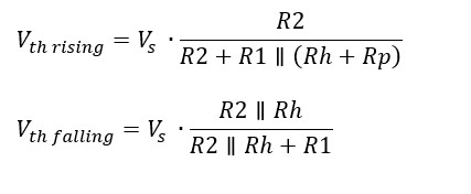
2.1.2. What Are the Formulas for Calculating Threshold Voltages?
The threshold voltages for an inverting comparator with hysteresis can be calculated using the following formulas:
- Upper Threshold (V+): (V{+} = V{ref} + frac{R_1}{R_1 + Rh} (V{outHigh} – V_{ref}))
- Lower Threshold (V-): (V{-} = V{ref} + frac{R_1}{R_1 + Rh} (V{outLow} – V_{ref}))
Where:
- (V_{ref}) is the reference voltage.
- (R_1) is the resistor connected between the non-inverting input and the reference voltage source.
- (R_h) is the hysteresis resistor.
- (V_{outHigh}) is the high output voltage.
- (V_{outLow}) is the low output voltage.
2.2. What is a Non-Inverting Comparator with Hysteresis?
In a non-inverting comparator with hysteresis, the input voltage (Vin) is applied to the non-inverting input of the op-amp, while the reference voltage is applied to the inverting input. The output switches high when Vin exceeds the upper threshold (V+) and switches low when Vin falls below the lower threshold (V-).
2.2.1. How Does the Non-Inverting Configuration Work?
In the non-inverting configuration, the reference voltage is applied to the inverting input. The hysteresis is introduced by feeding a portion of the output voltage back to the non-inverting input via a resistor (Rh). When the output is high, the feedback increases the voltage at the non-inverting input, raising the upper threshold (V+). When the output is low, the feedback decreases the voltage at the non-inverting input, lowering the lower threshold (V-).
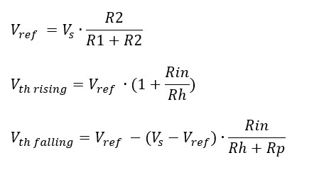
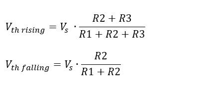
2.2.2. What Are the Formulas for Calculating Threshold Voltages?
The threshold voltages for a non-inverting comparator with hysteresis can be calculated using the following formulas:
- Upper Threshold (V+): (V{+} = V{ref} + frac{R_1}{R_2 + Rh} (V{outHigh} – V_{ref}))
- Lower Threshold (V-): (V{-} = V{ref} + frac{R_1}{R_2 + Rh} (V{outLow} – V_{ref}))
Where:
- (V_{ref}) is the reference voltage.
- (R_1) is the resistor connected between the non-inverting input and the output.
- (R_2) is the resistor connected between the non-inverting input and ground.
- (R_h) is the hysteresis resistor.
- (V_{outHigh}) is the high output voltage.
- (V_{outLow}) is the low output voltage.
2.3. What are the advantages and disadvantages of each configuration?
Each configuration—inverting and non-inverting—has specific advantages and disadvantages that make them suitable for different applications.
| Feature | Inverting Comparator | Non-Inverting Comparator |
|---|---|---|
| Input Impedance | High | Lower, varies with output state |
| Threshold Voltage | Set by voltage divider and feedback | Set by voltage divider and feedback |
| Noise Immunity | Excellent | Excellent |
| Output Polarity | Inverted relative to input | Same polarity as input |
| Complexity | Simpler circuit | More complex, especially with source impedance considerations |
| Applications | General-purpose, signal conditioning, level detection | Applications requiring non-inverted output |
| Source Impedance | Less sensitive to source impedance | More sensitive to source impedance |
3. How do you Design a Comparator Circuit with Hysteresis?
Designing a comparator circuit with hysteresis involves selecting appropriate component values to achieve the desired threshold voltages and hysteresis band. This section provides a step-by-step guide to designing both inverting and non-inverting comparators.
3.1. What are the Steps to Design an Inverting Comparator with Hysteresis?
-
Determine the Required Threshold Voltages (V+ and V-): Based on the application requirements, define the upper and lower threshold voltages.
-
Choose a Reference Voltage (Vref): Select a reference voltage that falls between V+ and V-.
-
Select a Resistor Value for R1: Choose a suitable value for R1, typically in the range of 1 kΩ to 10 kΩ.
-
Calculate the Value of Rh: Use the threshold voltage equations to calculate the required value of Rh.
Rearrange the equations to solve for Rh:- (R_h = frac{R1 (V{outHigh} – V{ref})}{V{+} – V_{ref}} – R_1)
- (R_h = frac{R1 (V{outLow} – V{ref})}{V{-} – V_{ref}} – R_1)
Average the two calculated values of Rh to account for variations in component tolerances.
-
Verify the Design: Simulate the circuit using circuit simulation software (e.g., LTspice) to verify that the threshold voltages and hysteresis band meet the design requirements.
3.2. What are the Steps to Design a Non-Inverting Comparator with Hysteresis?
-
Determine the Required Threshold Voltages (V+ and V-): Based on the application requirements, define the upper and lower threshold voltages.
-
Choose a Reference Voltage (Vref): Select a reference voltage that falls between V+ and V-.
-
Select a Resistor Value for R1: Choose a suitable value for R1, typically in the range of 1 kΩ to 10 kΩ.
-
Calculate the Value of R2: Use the following equation: (V{ref} = V{cc} cdot frac{R_2}{R_1 + R2}), where (V{cc}) is the supply voltage.
Solve for (R_2): (R_2 = frac{R1 cdot V{ref}}{V{cc} – V{ref}}) -
Calculate the Value of Rh: Use the threshold voltage equations to calculate the required value of Rh. Rearrange the equations to solve for Rh:
- (R_h = frac{R1 (V{outHigh} – V{ref})}{V{+} – V_{ref}} – R_2)
- (R_h = frac{R1 (V{outLow} – V{ref})}{V{-} – V_{ref}} – R_2)
Average the two calculated values of Rh to account for variations in component tolerances.
-
Verify the Design: Simulate the circuit using circuit simulation software (e.g., LTspice) to verify that the threshold voltages and hysteresis band meet the design requirements.
3.3. What are Important Considerations for Component Selection?
- Op-Amp Characteristics: Choose an op-amp with suitable characteristics, such as input bias current, input offset voltage, and slew rate. Low input bias current and offset voltage are crucial for accurate threshold detection. The slew rate should be high enough to handle the expected input signal frequency.
- Resistor Tolerance: Use resistors with low tolerance (e.g., 1%) to ensure accurate threshold voltages.
- Power Supply: Ensure that the power supply voltage is stable and within the operating range of the op-amp.
4. What are the Applications of Comparators with Hysteresis?
Comparators with hysteresis are used in a wide range of applications, including signal conditioning, threshold detection, and noise reduction. Their ability to provide stable switching in noisy environments makes them essential in many electronic systems.
4.1. How Are They Used in Signal Conditioning?
In signal conditioning, comparators with hysteresis are used to clean up noisy signals and convert them into clean digital signals. For example, in a sensor interface, the output of a sensor may be noisy or have slow transitions. A comparator with hysteresis can be used to convert this signal into a clean digital signal that can be processed by a microcontroller or other digital circuit.
4.2. How Are They Used in Threshold Detection?
Comparators with hysteresis are ideal for threshold detection applications where a specific voltage level needs to be detected reliably. Examples include:
- Over-Voltage Protection: Detecting when a voltage exceeds a safe level and triggering a protection circuit.
- Under-Voltage Detection: Detecting when a voltage drops below a critical level and initiating a shutdown sequence.
- Battery Monitoring: Monitoring the voltage of a battery and providing an alert when the battery is low.
4.3. How Are They Used in Noise Reduction?
The hysteresis feature of these comparators makes them excellent for noise reduction in various electronic systems. By introducing a hysteresis band, the comparator ignores small voltage fluctuations or noise around the threshold voltage, preventing false triggering and ensuring stable operation.
4.4. What are Some Specific Real-World Examples?
-
Thermostats: In thermostats, a comparator with hysteresis is used to control the heating or cooling system. The hysteresis prevents the system from rapidly switching on and off when the temperature is near the setpoint.
-
Motion Detectors: In motion detectors, a comparator with hysteresis can be used to detect changes in infrared radiation. The hysteresis prevents the detector from being triggered by small changes in radiation caused by noise or environmental factors.
-
Industrial Control Systems: In industrial control systems, comparators with hysteresis are used to monitor various parameters, such as pressure, temperature, and flow rate. The hysteresis ensures that the control system operates reliably in noisy industrial environments.
5. What are Some Advanced Techniques and Considerations?
Beyond the basic design principles, there are several advanced techniques and considerations that can further optimize the performance of comparators with hysteresis.
5.1. How Can You Adjust Hysteresis Levels Dynamically?
In some applications, it may be necessary to adjust the hysteresis levels dynamically based on changing conditions. This can be achieved by using a microcontroller or other digital circuit to control the reference voltage or the value of the hysteresis resistor. For example, in a battery monitoring system, the hysteresis levels may be adjusted based on the battery’s state of charge to provide more accurate alerts.
5.2. What is the Impact of Op-Amp Selection on Performance?
The choice of op-amp can significantly impact the performance of the comparator circuit. Key parameters to consider include:
- Input Bias Current: Low input bias current is essential for accurate threshold detection, especially when using high-value resistors.
- Input Offset Voltage: Low input offset voltage minimizes errors in the threshold voltages.
- Slew Rate: The slew rate should be high enough to handle the expected input signal frequency.
- Response Time: The response time of the op-amp determines how quickly the comparator can switch states.
5.3. How Do You Mitigate the Effects of Input Bias Current?
Input bias current can cause errors in the threshold voltages, especially when using high-value resistors. To mitigate these effects, consider using op-amps with low input bias current or compensating for the bias current by adding a compensating resistor in series with the non-inverting input.
5.4. What are the Trade-Offs Between Speed and Accuracy?
There is often a trade-off between speed and accuracy in comparator design. High-speed comparators typically have lower accuracy, while high-accuracy comparators tend to be slower. The choice between speed and accuracy depends on the specific application requirements. For example, in high-speed data acquisition systems, speed may be more critical than accuracy, while in precision measurement systems, accuracy is paramount.
6. Comparator with Hysteresis vs. Standard Comparator: What’s the Difference?
The primary distinction between a comparator with hysteresis and a standard comparator lies in their response to input voltage variations near the threshold. Standard comparators have a single switching point, making them highly susceptible to noise and oscillations. Comparators with hysteresis, on the other hand, introduce two distinct threshold voltages, creating a hysteresis band that prevents rapid switching and enhances stability in noisy environments. COMPARE.EDU.VN provides detailed comparisons of these types of comparators, including specifications and use cases.
6.1. What are the Key Differences in Behavior?
The table below summarizes the key differences in behavior between a comparator with hysteresis and a standard comparator:
| Feature | Standard Comparator | Comparator with Hysteresis |
|---|---|---|
| Switching Threshold | Single threshold | Two thresholds (upper and lower) |
| Noise Sensitivity | Highly sensitive to noise near the threshold | Less sensitive to noise due to the hysteresis band |
| Output Stability | Prone to oscillations and chattering | More stable output |
| Response to Input Change | Immediate switch at the threshold | Switch only when input crosses the respective threshold |
| Applications | Ideal for clean signal environments | Suitable for noisy environments and critical applications |
6.2. When Should You Use a Comparator With Hysteresis?
A comparator with hysteresis is most suitable for applications where noise is present in the input signal or where stable switching is required. Some specific scenarios include:
- Industrial Environments: Where electrical noise is prevalent.
- Sensor Interfaces: Where sensor outputs may be noisy.
- Control Systems: Where stability is crucial to prevent oscillations.
- Battery Monitoring: Where voltage levels need to be detected reliably.
- Any Application: Where false triggering due to noise must be avoided.
6.3. When is a Standard Comparator Sufficient?
A standard comparator is sufficient for applications where the input signal is clean and noise-free. These include:
- Precise Timing Circuits: Where accurate switching at a specific voltage is required.
- Simple Logic Gates: Where noise is minimal and signals are well-defined.
- Ideal Laboratory Conditions: Where noise can be controlled.
7. What are Some Common Pitfalls to Avoid?
Designing and implementing comparator circuits with hysteresis can present several challenges. Avoiding common pitfalls is essential for ensuring optimal performance.
7.1. How Do You Prevent Oscillations Due to Parasitic Capacitance?
Parasitic capacitance can cause oscillations in comparator circuits, especially at high frequencies. To prevent these oscillations, consider the following techniques:
-
Use a Decoupling Capacitor: Place a decoupling capacitor (e.g., 0.1 μF) close to the power supply pins of the op-amp.
-
Minimize Lead Lengths: Keep lead lengths as short as possible to reduce inductance.
-
Use a Ground Plane: Use a ground plane to provide a low-impedance path for return currents.
7.2. How Do You Handle Input Offset Voltage?
Input offset voltage can cause errors in the threshold voltages. To minimize these errors:
-
Use an Op-Amp with Low Input Offset Voltage: Select an op-amp with low input offset voltage.
-
Use Offset Nulling Techniques: Some op-amps provide offset nulling pins that can be used to adjust the offset voltage.
7.3. What About the Effects of Temperature Drift?
Temperature drift can cause variations in the threshold voltages and hysteresis band. To minimize the effects of temperature drift:
- Use Stable Resistors: Use resistors with low temperature coefficients.
- Design for Thermal Stability: Ensure that the circuit is designed to minimize temperature gradients.
8. Where Can You Find Comparator ICs with Built-In Hysteresis?
Many manufacturers offer comparator ICs with built-in hysteresis, which can simplify the design process and improve performance.
8.1. What are Some Popular Comparator ICs?
- Texas Instruments: LM393, LM339
- Analog Devices: ADCMP600, ADCMP601
- Maxim Integrated: MAX9021, MAX9022
COMPARE.EDU.VN provides detailed specifications and comparisons of these and other comparator ICs to help you find the best option for your application.
8.2. What are the Key Features to Look For?
When selecting a comparator IC with built-in hysteresis, consider the following features:
- Supply Voltage Range: Ensure that the supply voltage range is compatible with your application.
- Input Voltage Range: Verify that the input voltage range is sufficient for your application.
- Response Time: Consider the response time if speed is critical.
- Hysteresis Voltage: Check the hysteresis voltage to ensure it meets your noise immunity requirements.
- Output Type: Select an output type (e.g., open-collector, push-pull) that is compatible with your application.
9. What is the Future of Comparator Technology?
Comparator technology continues to evolve, with ongoing advancements in speed, accuracy, and power efficiency.
9.1. What are the Emerging Trends in Comparator Design?
- Low-Power Comparators: There is a growing demand for low-power comparators for battery-powered devices and energy-efficient systems.
- High-Speed Comparators: High-speed comparators are needed for applications such as high-speed data acquisition and communication systems.
- Precision Comparators: Precision comparators with low offset voltage and drift are essential for applications such as precision measurement and instrumentation.
9.2. How are Comparators Being Integrated into Systems-on-Chip (SoCs)?
Comparators are increasingly being integrated into Systems-on-Chip (SoCs) to provide on-chip signal conditioning and threshold detection capabilities. This integration can reduce system size, cost, and power consumption.
10. FAQs About Comparators with Hysteresis
To further clarify the topic, here are some frequently asked questions about comparators with hysteresis:
10.1. Why is Hysteresis Important in a Comparator?
Hysteresis is important because it prevents rapid switching and oscillations in noisy environments, ensuring a stable and reliable output.
10.2. How Does Hysteresis Improve Noise Immunity?
Hysteresis improves noise immunity by creating a gap between the switching thresholds, preventing the comparator from reacting to small voltage fluctuations caused by noise.
10.3. Can Hysteresis Be Adjusted in a Comparator Circuit?
Yes, the hysteresis level can be adjusted by changing the value of the feedback resistor (Rh) in the comparator circuit.
10.4. What is the Difference Between Inverting and Non-Inverting Comparators?
Inverting comparators produce an output that is inverted relative to the input, while non-inverting comparators produce an output with the same polarity as the input.
10.5. How Do I Choose the Right Op-Amp for a Comparator Circuit?
Choose an op-amp with low input bias current, low input offset voltage, and a slew rate that is suitable for your application.
10.6. What are Some Common Applications of Comparators with Hysteresis?
Common applications include signal conditioning, threshold detection, noise reduction, thermostats, motion detectors, and industrial control systems.
10.7. How Can I Prevent Oscillations in a Comparator Circuit?
Prevent oscillations by using decoupling capacitors, minimizing lead lengths, and using a ground plane.
10.8. What are Some Advantages of Using Comparator ICs with Built-In Hysteresis?
Comparator ICs with built-in hysteresis simplify the design process, improve performance, and save board space.
10.9. How Does Temperature Drift Affect Comparator Performance?
Temperature drift can cause variations in the threshold voltages and hysteresis band. Use stable resistors and design for thermal stability to minimize these effects.
10.10. Are Comparators Suitable for High-Frequency Applications?
Yes, but you need to choose a comparator with a high slew rate and consider the effects of parasitic capacitance to prevent oscillations.
Conclusion: Make Informed Decisions with COMPARE.EDU.VN
Understanding comparators with hysteresis is essential for designing robust and reliable electronic systems. By carefully selecting components, implementing appropriate design techniques, and avoiding common pitfalls, you can create comparator circuits that meet the demands of your application. Whether you’re working on signal conditioning, threshold detection, or noise reduction, comparators with hysteresis provide a powerful tool for achieving stable and accurate performance.
Ready to explore more about comparators and other electronic components? Visit COMPARE.EDU.VN today for detailed comparisons, expert insights, and resources to help you make informed decisions.
For further assistance and personalized recommendations, contact us:
Address: 333 Comparison Plaza, Choice City, CA 90210, United States
WhatsApp: +1 (626) 555-9090
Website: COMPARE.EDU.VN
Discover the best solutions with compare.edu.vn and take your electronics projects to the next level.