A 4-bit equality comparator truth table is a representation of a digital circuit that determines if two 4-bit binary numbers are equal; COMPARE.EDU.VN provides detailed comparisons and analysis to understand the logic behind this essential digital component, which is crucial in various applications like processors and control systems. This involves understanding binary arithmetic, logic gate functions, and combinational logic.
1. Understanding Digital Comparators
A digital comparator is a combinational logic circuit that compares two binary numbers to determine their relationship. The output of a comparator indicates whether the first number is greater than, less than, or equal to the second number. These circuits are fundamental components in various digital systems, including microprocessors, control systems, and arithmetic logic units (ALUs).
1.1. Types of Digital Comparators
Digital comparators can be broadly classified based on the number of bits they compare and the type of comparison they perform:
- 1-Bit Comparator: Compares two single-bit binary numbers.
- 2-Bit Comparator: Compares two 2-bit binary numbers.
- 4-Bit Comparator: Compares two 4-bit binary numbers.
- 8-Bit Comparator: Compares two 8-bit binary numbers.
- Equality Comparator: Determines only if two numbers are equal.
- Magnitude Comparator: Determines if one number is greater than, less than, or equal to another.
1.2. Applications of Digital Comparators
Digital comparators find applications in a wide array of digital systems due to their ability to perform real-time comparisons. Key applications include:
- Processors: Used in the instruction fetch and execute stages to compare addresses and data.
- Control Systems: Utilized for decision-making based on input signal levels.
- Arithmetic Logic Units (ALUs): Essential for performing arithmetic and logical operations.
- Memory Addressing: Employed to select specific memory locations based on address comparisons.
- Data Sorting: Used in algorithms to sort data based on numerical values.
- Analog-to-Digital Converters (ADCs): Comparators are a crucial component in many ADC designs, especially flash ADCs.
2. Basic Logic Gates Used in Comparators
Digital comparators are constructed using basic logic gates such as AND, OR, NOT, XOR, and XNOR gates. Understanding the behavior of these gates is essential for designing and analyzing comparator circuits.
2.1. AND Gate
The AND gate outputs a HIGH signal (1) only when all its inputs are HIGH (1). Otherwise, the output is LOW (0).
| Input A | Input B | Output (A AND B) |
|---|---|---|
| 0 | 0 | 0 |
| 0 | 1 | 0 |
| 1 | 0 | 0 |
| 1 | 1 | 1 |
2.2. OR Gate
The OR gate outputs a HIGH signal (1) if at least one of its inputs is HIGH (1). The output is LOW (0) only when all inputs are LOW (0).
| Input A | Input B | Output (A OR B) |
|---|---|---|
| 0 | 0 | 0 |
| 0 | 1 | 1 |
| 1 | 0 | 1 |
| 1 | 1 | 1 |
2.3. NOT Gate
The NOT gate, also known as an inverter, outputs the opposite of its input. If the input is HIGH (1), the output is LOW (0), and vice versa.
| Input A | Output (NOT A) |
|---|---|
| 0 | 1 |
| 1 | 0 |
2.4. XOR Gate
The XOR (Exclusive OR) gate outputs a HIGH signal (1) only when its inputs are different. If the inputs are the same, the output is LOW (0).
| Input A | Input B | Output (A XOR B) |
|---|---|---|
| 0 | 0 | 0 |
| 0 | 1 | 1 |
| 1 | 0 | 1 |
| 1 | 1 | 0 |
2.5. XNOR Gate
The XNOR (Exclusive NOR) gate outputs a HIGH signal (1) only when its inputs are the same. If the inputs are different, the output is LOW (0). The XNOR gate is the complement of the XOR gate.
| Input A | Input B | Output (A XNOR B) |
|---|---|---|
| 0 | 0 | 1 |
| 0 | 1 | 0 |
| 1 | 0 | 0 |
| 1 | 1 | 1 |
3. Designing a 1-Bit Comparator
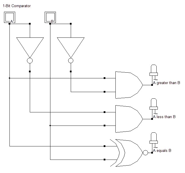
A 1-bit comparator compares two single-bit inputs, A and B, and produces three outputs: A > B, A < B, and A = B. The design involves using basic logic gates to implement the necessary logical expressions.
3.1. Truth Table for a 1-Bit Comparator
The truth table for a 1-bit comparator summarizes all possible input combinations and their corresponding outputs.
| A | B | A > B | A < B | A = B |
|---|---|---|---|---|
| 0 | 0 | 0 | 0 | 1 |
| 0 | 1 | 0 | 1 | 0 |
| 1 | 0 | 1 | 0 | 0 |
| 1 | 1 | 0 | 0 | 1 |
3.2. Logical Expressions
From the truth table, the logical expressions for each output can be derived:
- A > B: This is true only when A = 1 and B = 0. Therefore, the expression is A * B’.
- A < B: This is true only when A = 0 and B = 1. Therefore, the expression is A’ * B.
- A = B: This is true when A and B are either both 0 or both 1. Therefore, the expression is (A’ B’) + (A B), which is equivalent to A XNOR B.
3.3. Circuit Implementation
The 1-bit comparator circuit can be implemented using AND, NOT, and XNOR gates based on the derived logical expressions.
4. Designing a 2-Bit Comparator
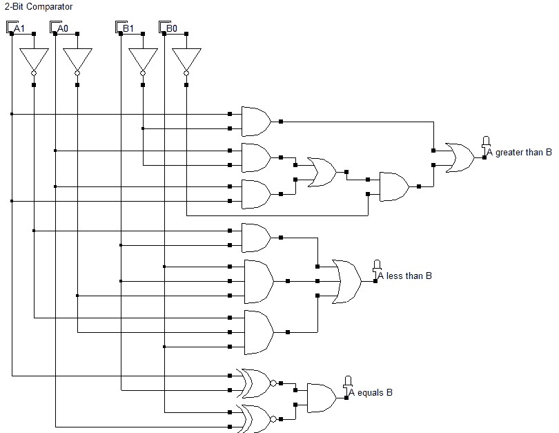
A 2-bit comparator compares two 2-bit binary numbers, A1A0 and B1B0, and determines whether A is greater than, less than, or equal to B. The design process is more complex than that of a 1-bit comparator due to the increased number of input combinations.
4.1. Truth Table for a 2-Bit Comparator
The truth table for a 2-bit comparator lists all possible combinations of A1A0 and B1B0 and their corresponding outputs.
| A1 | A0 | B1 | B0 | A > B | A < B | A = B |
|---|---|---|---|---|---|---|
| 0 | 0 | 0 | 0 | 0 | 0 | 1 |
| 0 | 0 | 0 | 1 | 0 | 1 | 0 |
| 0 | 0 | 1 | 0 | 0 | 1 | 0 |
| 0 | 0 | 1 | 1 | 0 | 1 | 0 |
| 0 | 1 | 0 | 0 | 1 | 0 | 0 |
| 0 | 1 | 0 | 1 | 0 | 0 | 1 |
| 0 | 1 | 1 | 0 | 0 | 1 | 0 |
| 0 | 1 | 1 | 1 | 0 | 1 | 0 |
| 1 | 0 | 0 | 0 | 1 | 0 | 0 |
| 1 | 0 | 0 | 1 | 1 | 0 | 0 |
| 1 | 0 | 1 | 0 | 0 | 0 | 1 |
| 1 | 0 | 1 | 1 | 0 | 1 | 0 |
| 1 | 1 | 0 | 0 | 1 | 0 | 0 |
| 1 | 1 | 0 | 1 | 1 | 0 | 0 |
| 1 | 1 | 1 | 0 | 1 | 0 | 0 |
| 1 | 1 | 1 | 1 | 0 | 0 | 1 |
4.2. Logical Expressions
Deriving logical expressions directly from the truth table can be complex. Karnaugh maps (K-maps) are often used to simplify the Boolean expressions. Using K-maps, we can obtain the following expressions:
- A > B: A1 B1′ + (A1 XNOR B1) A0 * B0′
- A < B: A1′ B1 + (A1 XNOR B1) A0′ * B0
- A = B: (A1 XNOR B1) * (A0 XNOR B0)
4.3. Circuit Implementation
The 2-bit comparator circuit can be implemented using AND, NOT, XOR, and XNOR gates based on the simplified logical expressions.
5. Designing a 4-Bit Comparator
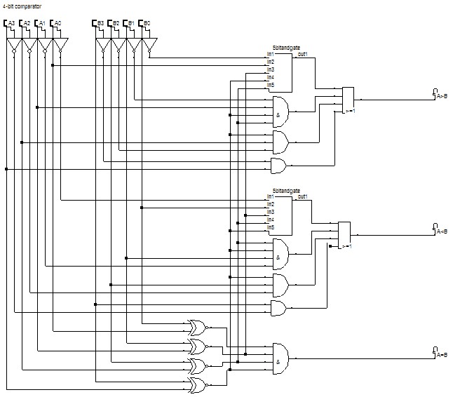
A 4-bit comparator compares two 4-bit binary numbers, A3A2A1A0 and B3B2B1B0. Due to the large number of input combinations (2^8 = 256), creating a full truth table is impractical. Instead, a hierarchical approach is used, comparing bits from the most significant bit (MSB) to the least significant bit (LSB).
5.1. Conceptual Truth Table for a 4-Bit Comparator
A simplified truth table can be constructed to illustrate the comparison process without listing all 256 rows.
| A3B3 | A2B2 | A1B1 | A0B0 | A > B | A < B | A = B |
|---|---|---|---|---|---|---|
| A3 > B3 | x | x | x | 1 | 0 | 0 |
| A3 < B3 | x | x | x | 0 | 1 | 0 |
| A3 = B3 | A2 > B2 | x | x | 1 | 0 | 0 |
| A3 = B3 | A2 < B2 | x | x | 0 | 1 | 0 |
| A3 = B3 | A2 = B2 | A1 > B1 | x | 1 | 0 | 0 |
| A3 = B3 | A2 = B2 | A1 < B1 | x | 0 | 1 | 0 |
| A3 = B3 | A2 = B2 | A1 = B1 | A0 > B0 | 1 | 0 | 0 |
| A3 = B3 | A2 = B2 | A1 = B1 | A0 < B0 | 0 | 1 | 0 |
| A3 = B3 | A2 = B2 | A1 = B1 | A0 = B0 | 0 | 0 | 1 |
5.2. Logical Expressions
The logical expressions for the 4-bit comparator can be derived based on the hierarchical comparison:
- A > B: (A3 B3′) + (A3 XNOR B3) (A2 B2′) + (A3 XNOR B3) (A2 XNOR B2) (A1 B1′) + (A3 XNOR B3) (A2 XNOR B2) (A1 XNOR B1) (A0 B0′)
- A < B: (A3′ B3) + (A3 XNOR B3) (A2′ B2) + (A3 XNOR B3) (A2 XNOR B2) (A1′ B1) + (A3 XNOR B3) (A2 XNOR B2) (A1 XNOR B1) (A0′ B0)
- A = B: (A3 XNOR B3) (A2 XNOR B2) (A1 XNOR B1) * (A0 XNOR B0)
5.3. Circuit Implementation
The 4-bit comparator circuit is constructed using a combination of AND, OR, NOT, and XNOR gates to implement the derived logical expressions. The circuit can be visualized as a cascade of comparisons from the MSB to the LSB.
6. 4-Bit Equality Comparator
An equality comparator is a simplified version of a magnitude comparator, designed only to determine if two binary numbers are equal. This type of comparator is commonly used in applications where only equality needs to be checked, simplifying the circuit design.
6.1. Truth Table for a 4-Bit Equality Comparator
For a 4-bit equality comparator, the output is HIGH (1) only when all corresponding bits of the two input numbers are equal. Otherwise, the output is LOW (0).
| A3 | A2 | A1 | A0 | B3 | B2 | B1 | B0 | A = B |
|---|---|---|---|---|---|---|---|---|
| 0 | 0 | 0 | 0 | 0 | 0 | 0 | 0 | 1 |
| 0 | 0 | 0 | 0 | 0 | 0 | 0 | 1 | 0 |
| 0 | 0 | 0 | 0 | 0 | 0 | 1 | 0 | 0 |
| … | … | … | … | … | … | … | … | … |
| 1 | 1 | 1 | 1 | 1 | 1 | 1 | 1 | 1 |
6.2. Logical Expression
The logical expression for a 4-bit equality comparator can be derived using XNOR gates. Each pair of corresponding bits is fed into an XNOR gate, and the outputs of these XNOR gates are then ANDed together. The expression is:
A = B = (A3 XNOR B3) (A2 XNOR B2) (A1 XNOR B1) * (A0 XNOR B0)
6.3. Circuit Implementation
The circuit implementation involves using four XNOR gates and one 4-input AND gate. Each XNOR gate compares one bit pair, and the AND gate combines the outputs of the XNOR gates to produce the final equality output.
7. Detailed Design Steps for a 4-Bit Equality Comparator
To create a 4-bit equality comparator, follow these detailed design steps, which will help ensure the final circuit meets the required specifications.
7.1. Step 1: Define the Requirements
First, define the requirements for the comparator. In this case, the comparator should:
- Accept two 4-bit binary numbers as inputs: A3A2A1A0 and B3B2B1B0.
- Produce a single output that indicates whether the two numbers are equal (A = B).
7.2. Step 2: Select Logic Gates
Choose the appropriate logic gates. For an equality comparator, XNOR gates are used to compare each bit pair, and an AND gate is used to combine the results.
- Four XNOR gates (one for each bit pair).
- One 4-input AND gate.
7.3. Step 3: Draw the Logic Diagram
Draw the logic diagram showing the connections between the logic gates.
- XNOR Gates:
- Connect A3 and B3 to the first XNOR gate.
- Connect A2 and B2 to the second XNOR gate.
- Connect A1 and B1 to the third XNOR gate.
- Connect A0 and B0 to the fourth XNOR gate.
- AND Gate:
- Connect the outputs of all four XNOR gates to the inputs of the 4-input AND gate.
- The output of the AND gate is the final output (A = B).
7.4. Step 4: Write the Boolean Expression
Write the Boolean expression for the comparator:
A = B = (A3 XNOR B3) (A2 XNOR B2) (A1 XNOR B1) * (A0 XNOR B0)
7.5. Step 5: Create the Truth Table
Create a truth table to verify the design. Since there are 2^8 = 256 possible input combinations, it’s impractical to list all of them. Instead, focus on key scenarios to validate the design.
| A3 | A2 | A1 | A0 | B3 | B2 | B1 | B0 | A = B |
|---|---|---|---|---|---|---|---|---|
| 0 | 0 | 0 | 0 | 0 | 0 | 0 | 0 | 1 |
| 0 | 0 | 0 | 0 | 0 | 0 | 0 | 1 | 0 |
| 1 | 0 | 1 | 0 | 1 | 0 | 1 | 0 | 1 |
| 1 | 1 | 1 | 1 | 1 | 1 | 1 | 1 | 1 |
| 1 | 0 | 1 | 0 | 0 | 1 | 0 | 1 | 0 |
7.6. Step 6: Simulate the Circuit
Use circuit simulation software (e.g., Multisim, LTspice) to simulate the circuit and verify its functionality. Apply different input combinations and check if the output matches the truth table.
7.7. Step 7: Build and Test the Circuit (Optional)
If you have the necessary components and equipment, build the circuit on a breadboard and test it using a logic analyzer or multimeter to verify its behavior.
7.8. Step 8: Optimize the Design (Optional)
Optimize the design for performance, power consumption, or cost. This might involve using different types of logic gates or reducing the number of gates.
8. Advantages and Disadvantages of Different Comparator Designs
Different comparator designs offer various trade-offs in terms of complexity, speed, and power consumption.
8.1. 1-Bit Comparator
- Advantages:
- Simple design.
- Low gate count.
- Fast operation.
- Disadvantages:
- Limited to comparing single-bit numbers.
8.2. 2-Bit Comparator
- Advantages:
- More versatile than a 1-bit comparator.
- Still relatively simple.
- Disadvantages:
- More complex than a 1-bit comparator.
- Requires more logic gates.
8.3. 4-Bit Comparator
- Advantages:
- Suitable for comparing larger numbers.
- Disadvantages:
- Complex design.
- High gate count.
- Slower operation compared to 1-bit and 2-bit comparators.
8.4. 4-Bit Equality Comparator
- Advantages:
- Simpler than a full 4-bit magnitude comparator.
- Efficient for equality checks.
- Disadvantages:
- Only determines equality; cannot determine greater than or less than.
9. Practical Considerations for Implementing Comparators
When implementing comparators in real-world applications, several practical considerations must be taken into account.
9.1. Propagation Delay
Propagation delay is the time it takes for the output of a logic gate to respond to a change in its inputs. In comparators, especially those with multiple stages, the cumulative propagation delay can affect the overall performance. Shorter propagation delays result in faster comparison speeds.
9.2. Power Consumption
Power consumption is a critical factor, especially in battery-powered devices. Comparators with fewer logic gates and simpler designs generally consume less power. CMOS logic is often preferred for its low static power consumption.
9.3. Fan-Out
Fan-out refers to the number of logic gates that the output of a gate can drive. Exceeding the fan-out limit can degrade the signal and affect the reliability of the circuit. Buffers can be used to increase the fan-out capability.
9.4. Noise Margin
Noise margin is the amount of noise that a signal can tolerate without causing an incorrect output. Adequate noise margin is essential for reliable operation, especially in noisy environments. Proper grounding and shielding techniques can help improve noise margin.
9.5. Cost
The cost of the components is an important consideration in mass production. Simpler designs with fewer components are generally more cost-effective.
10. Advanced Comparator Designs
For high-performance applications, advanced comparator designs are employed to improve speed, accuracy, and power efficiency.
10.1. Parallel Comparators
Parallel comparators, also known as flash comparators, use a large number of comparators to simultaneously compare the input signal with a set of reference voltages. This results in very fast conversion speeds, but at the cost of increased complexity and power consumption.
10.2. Pipelined Comparators
Pipelined comparators divide the comparison process into multiple stages, allowing for higher throughput. Each stage performs a partial comparison, and the results are passed to the next stage. This technique is commonly used in high-speed ADCs.
10.3. Dynamic Comparators
Dynamic comparators use clocked operation to reduce power consumption. They are active only during the comparison phase and consume minimal power during the idle phase.
10.4. Low-Voltage Comparators
Low-voltage comparators are designed to operate at low supply voltages, making them suitable for battery-powered devices. These comparators often use specialized circuit techniques to maintain performance at low voltages.
11. Real-World Applications of Comparators
Comparators are essential components in a wide range of electronic systems. Understanding their applications can help in designing more efficient and effective circuits.
11.1. Analog-to-Digital Converters (ADCs)
Comparators are a key building block in ADCs. In flash ADCs, an array of comparators is used to convert an analog signal to a digital representation.
11.2. Voltage Level Detection
Comparators are used to detect voltage levels and trigger appropriate actions. For example, they can be used to monitor battery voltage and activate a low-battery warning when the voltage drops below a certain threshold.
11.3. Zero-Crossing Detection
Comparators can detect when an AC signal crosses zero, which is useful in many applications, such as phase-locked loops (PLLs) and motor control systems.
11.4. Window Comparators
Window comparators use two comparators to detect whether an input voltage is within a specified range or “window.” This is useful in applications such as process control and monitoring systems.
11.5. Overcurrent Protection
Comparators are used in overcurrent protection circuits to detect when the current exceeds a safe level and take action to prevent damage to the circuit.
12. Future Trends in Comparator Technology
Comparator technology is continually evolving to meet the demands of emerging applications.
12.1. Higher Speed and Resolution
There is a growing demand for comparators with higher speed and resolution to support high-speed data acquisition and signal processing applications.
12.2. Lower Power Consumption
Reducing power consumption is a key focus, especially for portable and battery-powered devices.
12.3. Integration with Advanced Technologies
Comparators are being integrated with advanced technologies such as FinFETs and 3D ICs to improve performance and reduce size.
12.4. Self-Calibration and Error Correction
Self-calibration and error correction techniques are being developed to improve the accuracy and reliability of comparators.
12.5. Artificial Intelligence (AI) Integration
AI is being used to optimize comparator designs and improve their performance in specific applications.
13. Common Issues and Troubleshooting
Even with careful design and implementation, comparators can sometimes exhibit issues. Here are some common problems and troubleshooting tips:
13.1. Oscillation
Comparators can sometimes oscillate due to noise or feedback. Adding hysteresis can help prevent oscillation.
13.2. Slow Response Time
Slow response time can be caused by high input capacitance or low drive strength. Reducing capacitance and increasing drive strength can improve response time.
13.3. Offset Voltage
Offset voltage is a small voltage difference between the inputs that can cause the comparator to trigger incorrectly. Calibration techniques can be used to reduce offset voltage.
13.4. Noise Sensitivity
Comparators can be sensitive to noise, which can cause false triggering. Shielding, filtering, and proper grounding can help reduce noise sensitivity.
13.5. Power Supply Issues
Power supply noise and voltage fluctuations can affect the performance of comparators. Using a stable and well-regulated power supply is essential.
14. Key Takeaways for Effective Comparator Design
To design effective comparators, consider the following key takeaways:
- Understand the Requirements: Clearly define the requirements for the comparator, including speed, accuracy, power consumption, and cost.
- Choose the Right Architecture: Select the appropriate comparator architecture based on the requirements.
- Minimize Propagation Delay: Optimize the design to minimize propagation delay.
- Reduce Power Consumption: Use low-power design techniques to reduce power consumption.
- Ensure Adequate Noise Margin: Provide adequate noise margin for reliable operation.
- Simulate and Test: Thoroughly simulate and test the design to verify its functionality.
- Optimize for Performance: Optimize the design for performance, cost, and reliability.
15. Conclusion: Mastering Comparator Design
Digital comparators are essential building blocks in many digital systems, providing the ability to compare binary numbers and make decisions based on the comparison results. Whether designing a simple 1-bit comparator or a complex 4-bit comparator, understanding the principles of logic gates, truth tables, and circuit implementation is crucial. By considering the practical aspects and advanced techniques discussed in this guide, designers can create efficient and reliable comparator circuits for a wide range of applications.
By following the detailed design steps and practical considerations outlined, you can develop efficient and reliable equality comparators for various applications. The key to successful comparator design is a thorough understanding of the underlying principles, careful component selection, and rigorous testing and optimization. Visit COMPARE.EDU.VN for more insights and comparative analyses.
Still struggling to compare different digital components? COMPARE.EDU.VN offers comprehensive comparisons to make your decision-making process easier! Check out our detailed analyses today.
Address: 333 Comparison Plaza, Choice City, CA 90210, United States
Whatsapp: +1 (626) 555-9090
Website: compare.edu.vn
16. Frequently Asked Questions (FAQs) About 4-Bit Equality Comparators
16.1. What Is a 4-Bit Equality Comparator?
A 4-bit equality comparator is a digital circuit that compares two 4-bit binary numbers and outputs a signal indicating whether they are equal. It is a fundamental component in digital systems for tasks such as address decoding, data validation, and control logic.
16.2. How Does a 4-Bit Equality Comparator Work?
A 4-bit equality comparator compares each bit of the two 4-bit numbers. It uses XNOR gates to compare corresponding bits and an AND gate to combine the outputs of the XNOR gates. The output is HIGH (1) only when all corresponding bits are equal, indicating that the two numbers are identical.
16.3. What Is the Truth Table for a 4-Bit Equality Comparator?
The truth table for a 4-bit equality comparator would have 2^8 = 256 rows, representing all possible combinations of the two 4-bit inputs. The output is 1 only when the two input numbers are equal and 0 otherwise. A simplified version is shown below:
| A3 | A2 | A1 | A0 | B3 | B2 | B1 | B0 | A = B |
|---|---|---|---|---|---|---|---|---|
| 0 | 0 | 0 | 0 | 0 | 0 | 0 | 0 | 1 |
| 0 | 0 | 0 | 0 | 0 | 0 | 0 | 1 | 0 |
| 1 | 0 | 1 | 0 | 1 | 0 | 1 | 0 | 1 |
| 1 | 1 | 1 | 1 | 1 | 1 | 1 | 1 | 1 |
16.4. What Logic Gates Are Used in a 4-Bit Equality Comparator?
The primary logic gates used in a 4-bit equality comparator are XNOR gates and an AND gate. Four XNOR gates compare each bit pair (A3 with B3, A2 with B2, A1 with B1, and A0 with B0), and a 4-input AND gate combines the outputs of the XNOR gates to produce the final equality output.
16.5. How Do You Design a 4-Bit Equality Comparator?
To design a 4-bit equality comparator:
- Use four XNOR gates to compare each bit pair of the two 4-bit numbers.
- Connect the outputs of the XNOR gates to the inputs of a 4-input AND gate.
- The output of the AND gate provides the equality signal, indicating whether the two numbers are equal.
16.6. What Is the Boolean Expression for a 4-Bit Equality Comparator?
The Boolean expression for a 4-bit equality comparator is:
A = B = (A3 XNOR B3) (A2 XNOR B2) (A1 XNOR B1) * (A0 XNOR B0)
16.7. What Are the Applications of 4-Bit Equality Comparators?
4-bit equality comparators are used in various applications, including:
- Address Decoding: Comparing memory addresses to select specific memory locations.
- Data Validation: Checking if received data matches expected data.
- Control Logic: Implementing control decisions based on data equality.
- Arithmetic Logic Units (ALUs): Performing equality checks in arithmetic operations.
16.8. How Is a 4-Bit Equality Comparator Different from a Magnitude Comparator?
A 4-bit equality comparator only determines if two numbers are equal, while a magnitude comparator determines if one number is greater than, less than, or equal to another. A magnitude comparator is more complex than an equality comparator, as it requires additional logic to perform the greater than and less than comparisons.
16.9. Can 4-Bit Equality Comparators Be Cascaded?
Yes, 4-bit equality comparators can be cascaded to compare larger binary numbers. To cascade comparators, connect the equality outputs of the individual comparators to the inputs of an additional AND gate. The final output of the AND gate indicates whether all the cascaded inputs are equal.
16.10. What Are Some Common Issues When Using 4-Bit Equality Comparators?
Some common issues when using 4-bit equality comparators include:
- Propagation Delay: The time it takes for the comparator to produce a valid output can affect performance.
- Noise Sensitivity: Comparators can be sensitive to noise, which can cause false triggering.
- Power Consumption: Complex comparators can consume significant power, especially in battery-powered devices.