Electrical circuits are the pathways that allow electricity to power our homes, devices, and countless technologies. Within these circuits, components can be arranged in different configurations, most commonly in series or parallel. Understanding the distinction between series and parallel circuits is fundamental to grasping basic electronics and how electrical devices function. This article will Compare And Contrast Series And Parallel Circuits, highlighting their key differences in current flow, voltage distribution, resistance, and practical applications.
Series Circuits: One Path for Electricity
In a series circuit, components are connected one after another along a single path. Imagine it as a single lane road where all cars (electrons) must follow each other in a line. This configuration has several defining characteristics:
Key Characteristics of Series Circuits
-
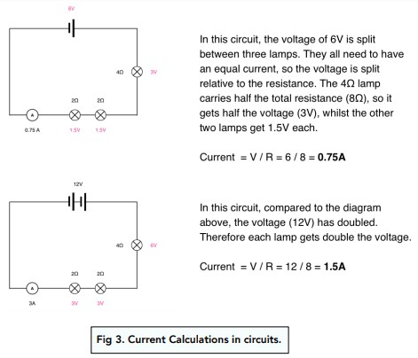
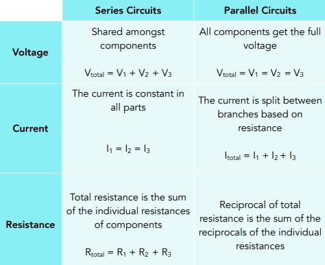
Consistent Current: The electric current is the same at every point in a series circuit. Because there’s only one path for electrons to flow, the rate of flow (current) must be consistent throughout. Think of water flowing through a single pipe – the amount of water passing any point in the pipe is the same.
-
Voltage Division: The total voltage supplied by the power source is divided among the components in the series circuit. Each component consumes a portion of the voltage. The sum of the voltage drops across each component equals the total voltage supplied. If you have a 12V battery and two identical bulbs in series, each bulb will receive 6V.
-
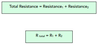
Additive Resistance: The total resistance in a series circuit is the sum of the individual resistances of all components. Adding more components in series increases the overall resistance of the circuit, making it harder for current to flow. This can be calculated with the simple formula:
Rtotal = R1 + R2 + R3 + …
Where Rtotal is the total resistance, and R1, R2, R3, etc., are the resistances of individual components.
-
Single Point of Failure: If there is a break or fault at any point in a series circuit, the entire circuit stops working. Because there is only one path, breaking the path at any point disrupts the flow of current to all components. Old-fashioned Christmas lights wired in series are a prime example – if one bulb burns out, the entire string goes dark.
-
Voltage Source Addition: If multiple voltage sources (like batteries) are connected in series, their voltages add up to provide a higher total voltage to the circuit. This is how flashlights often use multiple batteries in series to increase the voltage supplied to the bulb.
Parallel Circuits: Multiple Paths for Electricity
In contrast to series circuits, parallel circuits provide multiple paths for the electric current to flow. Imagine a multi-lane highway where cars can choose different routes to reach their destination. This configuration leads to a different set of characteristics:
Key Characteristics of Parallel Circuits
-
Consistent Voltage: The voltage across each component in a parallel circuit is the same and equal to the voltage supplied by the power source. Each branch of the parallel circuit receives the full voltage. Using the water analogy, imagine multiple pipes connected to the same water source – each pipe receives the same water pressure.
-
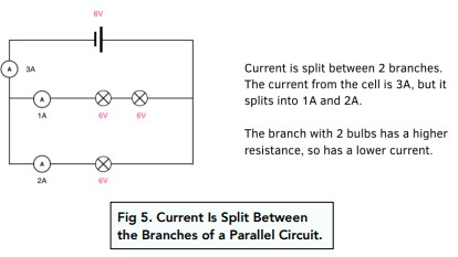
Current Division: The total current from the power source is divided among the different branches (paths) of a parallel circuit. The amount of current flowing through each branch depends on the resistance of that branch. The sum of the currents in each branch equals the total current leaving the power source.
-
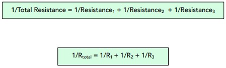
Reduced Total Resistance: Adding more branches (components) in parallel actually decreases the total resistance of the circuit. This is because providing more paths makes it easier for current to flow. The formula for calculating total resistance in a parallel circuit is:
1/Rtotal = 1/R1 + 1/R2 + 1/R3 + …
Where Rtotal is the total resistance, and R1, R2, R3, etc., are the resistances of individual components in each branch. This formula demonstrates that the reciprocal of the total resistance is the sum of the reciprocals of individual resistances.
-
Independent Branches: If one component fails or a branch is broken in a parallel circuit, the other branches continue to function. Because there are alternative paths for current, a break in one path does not disrupt the flow in others. This is why household wiring is typically in parallel – if a bulb burns out in one room, the lights in other rooms remain on.
-
Brightness Consistency: Bulbs connected in parallel, assuming they have similar resistance, will burn at the same brightness. This is because each bulb receives the full voltage from the source.
Resistors in Series and Parallel: Impact on Resistance
Resistors, components designed to oppose the flow of current, behave differently in series and parallel circuits, directly affecting the overall circuit resistance.
- Series Resistors Increase Resistance: In a series circuit, adding more resistors increases the total resistance. Each resistor adds to the obstruction of current flow, making it cumulatively harder for electrons to move through the circuit.
- Parallel Resistors Decrease Resistance: In a parallel circuit, adding more resistors decreases the total resistance. This might seem counterintuitive, but by providing more parallel paths, you effectively widen the “highway” for electrons, allowing more current to flow for the same voltage.
Calculating Equivalent Resistance: Simplifying Circuits
For circuit analysis, it’s often useful to calculate the equivalent resistance, which represents the total resistance of a combination of resistors as if they were a single resistor.
Series Resistance Calculation:
As mentioned earlier, the total resistance in a series circuit is simply the sum of individual resistances:
Rtotal = R1 + R2 + R3 + …
Example: If you have two resistors in series, R1 = 20 ohms and R2 = 10 ohms, the equivalent resistance is:
Rtotal = 20 ohms + 10 ohms = 30 ohms
Parallel Resistance Calculation:
For parallel circuits, we use the reciprocal formula:
1/Rtotal = 1/R1 + 1/R2 + 1/R3 + …
Example: If you have two resistors in parallel, R1 = 20 ohms and R2 = 10 ohms, the equivalent resistance is:
1/Rtotal = 1/20 ohms + 1/10 ohms = 3/20 ohms
Rtotal = 20/3 ohms ≈ 6.67 ohms
Notice that the total resistance in parallel (6.67 ohms) is less than the smallest individual resistance (10 ohms), as expected.
Practical Applications: Series vs. Parallel in Everyday Life
The distinct characteristics of series and parallel circuits make them suitable for different applications:
-
Series Circuits Applications:
- Fuses: Fuses are connected in series to protect circuits from overcurrent. If the current exceeds a safe limit, the fuse wire melts (breaks), interrupting the series circuit and stopping the current flow to prevent damage.
- Voltage Dividers: Series circuits with resistors can be used to create voltage dividers, which provide a fraction of the input voltage as output. This is used in electronic circuits to obtain specific voltage levels.
- Older Christmas Lights: As mentioned, older, less efficient Christmas light strings were often wired in series, primarily to save on wiring costs and utilize lower voltage bulbs.
-
Parallel Circuits Applications:
- Household Wiring: Homes are wired in parallel circuits so that appliances and lights can operate independently. You can switch off a lamp without affecting the refrigerator or other devices.
- Car Electrical Systems: Car headlights, interior lights, and other electrical components are connected in parallel to ensure that if one component fails, others continue to operate.
- Power Distribution: Electrical grids use parallel connections to distribute power efficiently to multiple users.
Advantages and Disadvantages: Choosing the Right Circuit
| Feature | Series Circuits | Parallel Circuits |
|---|---|---|
| Current | Constant throughout the circuit | Divides among branches |
| Voltage | Divides among components | Constant across all branches |
| Resistance | Total resistance is the sum of individual resistances | Total resistance is less than the smallest individual resistance |
| Component Failure | Circuit fails if one component breaks | Other branches continue to operate if one fails |
| Brightness (Bulbs) | Brightness varies based on resistance, dims with more bulbs | Consistent brightness for similar bulbs |
| Wiring Complexity | Simpler wiring | More complex wiring |
| Cost | Generally lower cost due to simpler wiring | Generally higher cost due to more complex wiring |
Investigating Resistance in Experiments
Understanding series and parallel circuits is reinforced through experimentation. Simple experiments can be designed to verify the principles of resistance in both circuit types.
Experiments with Series Circuits
- Setup: Construct a series circuit with a power source (battery), an ammeter (to measure current), and a resistor.
- Measurement: Measure and record the voltage of the power source and the current flowing through the circuit.
- Calculation: Calculate the resistance using Ohm’s Law (R = V/I).
- Adding Resistors: Add another resistor in series and repeat steps 2 and 3. Observe how the current decreases and the total resistance increases with each added resistor.
- Data Analysis: Plot a graph of the number of resistors versus total resistance. The graph should show a linear relationship, confirming that resistance increases linearly in a series circuit.
Experiments with Parallel Circuits
- Setup: Construct a parallel circuit with a power source, an ammeter (placed to measure the total current), and resistors connected in parallel branches.
- Measurement: Measure and record the voltage of the power source and the total current.
- Calculation: Calculate the total resistance using Ohm’s Law.
- Adding Resistors: Add another resistor in parallel (creating a new branch) and repeat steps 2 and 3. Observe how the total current increases and the total resistance decreases with each added parallel branch.
- Data Analysis: Analyze the data to observe the inverse relationship between the number of parallel branches and the total resistance.
Short Circuits: An Unintended Path
A short circuit occurs when an unintended path of very low resistance is created in a circuit, often bypassing the intended components. Current always takes the path of least resistance. If a short circuit path is available, most of the current will flow through it, potentially overloading the circuit and causing damage or fire hazards.
In the diagram, if switches P and Q are closed, the current bypasses the lamps because the plain wire offers a much lower resistance path. This demonstrates how a short circuit can prevent components from functioning and potentially cause dangerous situations.
Conclusion: Mastering Circuit Basics
Understanding the fundamental differences between series and parallel circuits is crucial for anyone studying electronics or simply wanting to comprehend how electrical devices work. Series circuits are characterized by a single path for current, voltage division, and additive resistance, while parallel circuits offer multiple paths, constant voltage, and reduced total resistance. Choosing between series and parallel configurations depends on the specific application and desired circuit behavior. By grasping these core concepts, you gain a solid foundation for exploring more complex electrical and electronic systems.
Frequently Asked Questions
→What are series circuits?
A series circuit is an electrical circuit where components are connected in a single path, one after another, so the same current flows through each component.
→What are parallel circuits?
A parallel circuit is an electrical circuit where components are connected in separate branches, each receiving the same voltage, allowing current to divide among the branches.
→How do series circuits differ from parallel circuits?
The key differences lie in current flow (same in series, divided in parallel), voltage distribution (divided in series, same in parallel), and the effect of component failure (entire series circuit breaks, only one branch affected in parallel).
→What happens to the total resistance in a series circuit?
The total resistance in a series circuit increases as you add more components; it is the sum of the individual resistances.
→What happens to the total resistance in a parallel circuit?
The total resistance in a parallel circuit decreases as you add more branches; it is always less than the smallest individual resistance.
→What happens to the total current in a series circuit?
The total current in a series circuit is the same as the current through any individual component.
→What happens to the total current in a parallel circuit?
The total current in a parallel circuit is the sum of the currents in each individual branch.
→Why are parallel circuits used more often than series circuits in everyday life?
Parallel circuits are more practical for everyday applications because they allow independent operation of components. If one component fails in a parallel circuit, the others can continue to function, which is essential for reliability in homes, cars, and most electrical systems.