This article addresses common questions from hobbyist electronics enthusiasts regarding the use of Comparator Op Amps in simple voltage sensing circuits. We’ll explore a practical example circuit designed to trigger a beep when a voltage threshold is crossed, and delve into the nuances of using op-amps versus dedicated comparators.
The original circuit in question is designed to monitor voltage levels using voltage dividers and signal an alert with a beeper. It’s powered by a 12V battery and intended for a niche sporting goods application. Let’s break down the circuit and address the key questions raised by the designer.
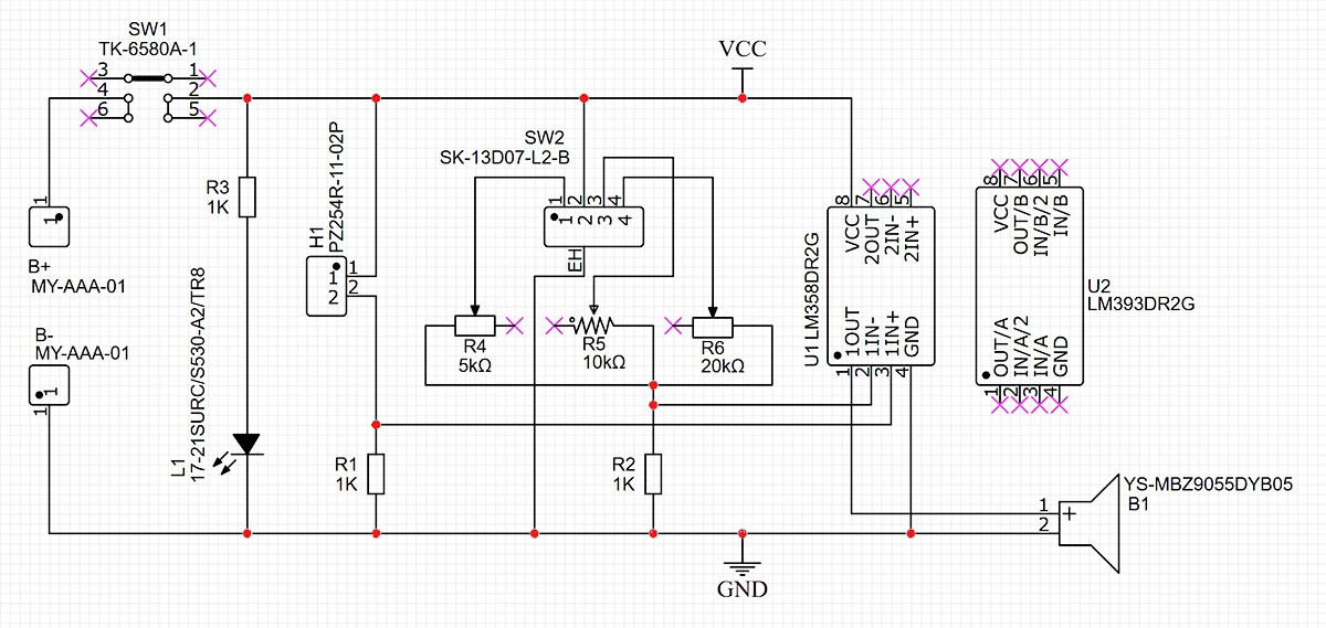
The circuit utilizes two voltage dividers. The first voltage divider employs a force-sensing resistor (FSR) and a fixed resistor (R1). The FSR’s resistance decreases with applied pressure, causing the voltage at the divider’s output to change. This acts as the sensor input.
The second voltage divider uses a 3-position switch connected to three potentiometers (R4, R5, R6) and a fixed resistor (R2). These potentiometers allow for fine-tuning three different voltage threshold levels, selectable via the switch. The circuit is designed so that when the voltage from the FSR voltage divider exceeds the voltage set by the potentiometer divider, a beeper sounds.
The designer initially implemented the circuit using an LM358P op-amp and observed that it functioned as intended. They then raised three specific questions concerning component choices and circuit behavior, which we will address in detail.
Op-Amp vs. Comparator: Is There a Difference?
The first key question is whether there’s a significant difference between using an op-amp (like the LM358P) and a dedicated comparator (like the LM393 shown in the schematic) for this voltage comparison application. While both devices can perform voltage comparison, they are optimized for different purposes and have distinct characteristics.
An operational amplifier (op-amp) is primarily designed for linear amplification. It excels at amplifying signals in a linear fashion, meaning the output signal is a scaled-up version of the input signal. While op-amps can be used as comparators in a pinch, they are not ideally suited for this task.
A comparator, on the other hand, is specifically designed for voltage comparison. Its internal circuitry is optimized for rapid switching between output states when the input voltages cross a threshold. Comparators typically have faster response times (propagation delay) and are designed to operate in saturation, meaning their output is driven to either the positive or negative supply rail, which is ideal for digital-like on/off switching actions needed for triggering a beeper.
For this specific application – simply detecting when one voltage exceeds another to trigger a beeper – a comparator is the more appropriate and often better choice. Using a comparator like the LM393 will generally result in cleaner and faster switching behavior compared to an op-amp used as a comparator. Furthermore, dedicated comparators often have open-collector outputs, which, as we’ll see, require a pull-up resistor for proper operation but offer flexibility in interfacing with different logic levels.
DIP vs. SMD Op-Amps: Any Performance Variations?
The second question concerns the difference between DIP (Dual In-line Package) and SMD (Surface Mount Device) versions of the op-amp. In this particular circuit and for typical hobbyist applications, there will be virtually no functional difference between using a DIP LM358P and an SMD LM358.
The core silicon die inside both packages is identical, meaning the fundamental electrical characteristics are the same. The difference lies solely in the packaging style. DIP packages are through-hole components, easier to prototype with on breadboards, while SMD packages are designed for surface mounting on PCBs, leading to more compact and efficient designs for mass production.
For low-frequency applications like this voltage comparator circuit, parasitic effects introduced by the different packages are negligible. In high-frequency or very sensitive applications, SMD components might offer slight advantages due to reduced lead inductance and capacitance, but these are not relevant considerations here. Therefore, the designer can confidently switch to the SMD op-amp (or comparator) for their PCB design without expecting any performance changes in the circuit’s basic functionality.
Resistor Values and Beeper Voltage: Impact Analysis
The final question revolves around the effect of changing the resistor values (R1 and R2) on the voltage seen by the beeper. It’s important to clarify that R1 and R2 do not directly control the voltage supplied to the beeper. Instead, they play a crucial role in setting the voltage thresholds at the inputs of the comparator (or op-amp).
R1 and the FSR form the first voltage divider, and their values determine the voltage range produced by the sensor. Similarly, R2 and the potentiometers form the second voltage divider, setting the reference voltage. Changing R1 and R2 will alter the voltage division ratios and therefore shift the voltage levels at the comparator’s inputs.
While changing R1 and R2 won’t directly make the beeper louder or quieter, they will affect the sensitivity and trigger points of the circuit. If R1 and R2 are significantly increased, the current through the voltage dividers will decrease, which might slightly increase the input impedance seen by the comparator, but in most practical scenarios with typical resistor values and comparator input impedances, this effect is minimal.
The loudness of the beeper is primarily determined by the voltage and current supplied to it from the output of the comparator (or op-amp) and the beeper’s own electrical characteristics. In the updated schematic, a pull-up resistor is added, which is essential when using a comparator with an open-collector output.
Implementing the Comparator and Pull-up Resistor
The updated schematic correctly incorporates an LM393 comparator and a pull-up resistor. Comparators like the LM393 often have an open-collector output. This means the output transistor acts like a switch that can only pull the output voltage down to ground (or close to it). It cannot actively drive the output voltage high.
Therefore, a pull-up resistor connected between the comparator’s output pin and the positive supply voltage is necessary. When the comparator’s output transistor is off (not conducting), the pull-up resistor pulls the output voltage high. When the comparator’s output transistor turns on (conducting), it pulls the output voltage low. This creates the necessary voltage swing to drive the beeper.
In conclusion, for a voltage sensing application like this, a dedicated comparator such as the LM393 is generally a more suitable choice than an op-amp. The SMD package version will function identically to the DIP version in this circuit. Adjusting R1 and R2 changes the voltage thresholds, not the beeper volume directly, and the addition of a pull-up resistor is crucial for proper operation with an open-collector comparator output. By understanding these nuances, hobbyist designers can optimize their circuits for better performance and reliability.