A Comparator With Hysteresis Has How Many Trigger Points? Understanding this question is crucial for anyone working with electronic circuits, especially those involving operational amplifiers and feedback mechanisms. At COMPARE.EDU.VN, we delve into the specifics of comparators with hysteresis, exploring their functionality, design, and applications to provide clarity and solutions. This article aims to offer a comprehensive overview that will significantly improve your understanding of comparator circuits, switching thresholds, and related concepts.
1. Introduction to Comparators and Hysteresis
A comparator is an electronic circuit that compares two input voltages and outputs a digital signal indicating which input is larger. It’s a fundamental building block in many electronic systems. The integration of hysteresis into a comparator circuit adds a valuable feature: noise immunity and stable switching behavior. Hysteresis introduces two different threshold voltages, one for the rising input signal and another for the falling input signal, thereby defining two trigger points. This characteristic significantly enhances the comparator’s performance in noisy environments. By understanding the role of trigger points, hysteresis width, and feedback resistors, one can design efficient comparator circuits.
1.1 What is a Comparator?
A comparator is a circuit that compares two voltages, producing a binary output. This output indicates whether the input voltage is greater than or less than a reference voltage. Comparators are commonly used in applications such as analog-to-digital converters (ADCs), zero-crossing detectors, and threshold detectors.
1.2 Understanding Hysteresis
Hysteresis is the dependence of a system on its past states. In the context of comparators, hysteresis means the switching threshold depends on the previous output state. This is achieved by adding positive feedback to the comparator circuit. The key components that contribute to hysteresis are feedback resistors and the operational amplifier itself.
1.3 Purpose of Hysteresis in Comparators
The primary purpose of incorporating hysteresis in a comparator is to prevent rapid, unwanted switching due to noise or small variations in the input signal near the threshold voltage. Without hysteresis, a noisy input signal hovering around the threshold could cause the comparator to switch rapidly between high and low states, leading to unstable and unreliable behavior.
2. The Role of Trigger Points in a Comparator with Hysteresis
In a comparator with hysteresis, the two trigger points define the upper and lower threshold voltages. These trigger points are critical for stable switching behavior, providing a buffer against noise and minor voltage fluctuations.
2.1 Defining Trigger Points
Trigger points, also known as threshold voltages, are the specific voltage levels at which the comparator output switches states. In a comparator with hysteresis, there are two trigger points:
- Upper Trigger Point (UTP): The voltage level at which the output switches from low to high.
- Lower Trigger Point (LTP): The voltage level at which the output switches from high to low.
2.2 How Hysteresis Creates Two Trigger Points
Hysteresis creates two trigger points by using positive feedback. When the output is high, the positive feedback increases the effective threshold voltage, requiring a higher input voltage to switch the output low. Conversely, when the output is low, the positive feedback decreases the effective threshold voltage, requiring a lower input voltage to switch the output high.
2.3 Importance of Two Trigger Points
Having two distinct trigger points is crucial for noise immunity. The difference between the UTP and LTP is known as the hysteresis width. This width provides a buffer zone, preventing the comparator from switching erratically when the input signal is near the threshold. The operational amplifier’s open-loop gain, combined with the feedback resistors, determines the precision and stability of these trigger points.
3. Circuit Configuration and Components
The design of a comparator with hysteresis involves several key components, including the operational amplifier (op-amp), feedback resistors, and input voltage source. Each component plays a vital role in defining the comparator’s behavior and performance.
3.1 Basic Circuit Diagram
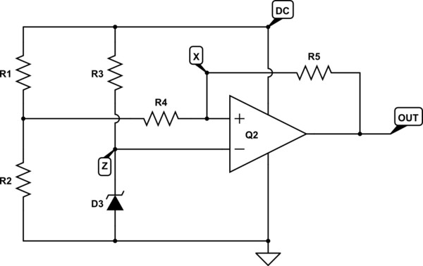
The basic circuit for a comparator with hysteresis typically includes an op-amp, two resistors (R1 and R2) forming a positive feedback network, and an input voltage signal. The op-amp compares the input voltage with a reference voltage, and the output is fed back through the resistors to the non-inverting input, creating hysteresis.
3.2 Role of Operational Amplifier (Op-Amp)
The operational amplifier is the core of the comparator circuit. It amplifies the voltage difference between its two inputs and provides a high-gain output. The op-amp’s characteristics, such as its open-loop gain and slew rate, affect the comparator’s switching speed and accuracy.
3.3 Feedback Resistors (R1 and R2)
The feedback resistors, R1 and R2, are essential for creating the hysteresis effect. These resistors form a positive feedback loop that shifts the threshold voltages based on the current output state. The ratio of R1 to R2 determines the width of the hysteresis.
3.4 Input Voltage Source
The input voltage source is the signal being compared against the reference. This can be any analog signal, and the comparator will output a digital signal based on whether the input voltage is above or below the defined trigger points.
4. Calculating Trigger Points
To design a comparator with hysteresis, it is essential to calculate the upper and lower trigger points accurately. These calculations depend on the supply voltage, feedback resistors, and reference voltage.
4.1 Formulas for UTP and LTP
The formulas for calculating the Upper Trigger Point (UTP) and Lower Trigger Point (LTP) are as follows:
-
Upper Trigger Point (UTP):
UTP = Vref + (R1 / (R1 + R2)) * (Vcc - Vref) -
Lower Trigger Point (LTP):
LTP = Vref - (R1 / (R1 + R2)) * (Vcc - Vref)Where:
Vrefis the reference voltage.Vccis the supply voltage.R1andR2are the feedback resistors.
4.2 Example Calculation
Let’s consider a comparator circuit with the following values:
Vref = 2.5VVcc = 5VR1 = 1kΩR2 = 10kΩ
Using the formulas above:
-
UTP:
UTP = 2.5V + (1kΩ / (1kΩ + 10kΩ)) * (5V - 2.5V) UTP = 2.5V + (1/11) * 2.5V UTP ≈ 2.5V + 0.227V UTP ≈ 2.727V -
LTP:
LTP = 2.5V - (1kΩ / (1kΩ + 10kΩ)) * (5V - 2.5V)
LTP = 2.5V - (1/11) * 2.5V
LTP ≈ 2.5V - 0.227V
LTP ≈ 2.273V
4.3 Factors Affecting Trigger Points
Several factors can affect the trigger points in a comparator circuit:
- Resistor Tolerance: Variations in resistor values due to manufacturing tolerances can shift the trigger points.
- Supply Voltage Fluctuations: Changes in the supply voltage (
Vcc) will directly impact the trigger points. - Op-Amp Characteristics: The op-amp’s input bias current and offset voltage can introduce errors in the threshold voltages.
5. Advantages of Using Hysteresis
Incorporating hysteresis into a comparator circuit provides numerous advantages, particularly in mitigating noise and ensuring stable switching behavior.
5.1 Noise Immunity
One of the most significant advantages of hysteresis is its ability to improve noise immunity. The hysteresis width creates a buffer zone that prevents the comparator from reacting to small, noisy fluctuations around the threshold voltage.
5.2 Stable Switching Behavior
Hysteresis ensures stable switching behavior by preventing rapid oscillations between high and low states. This is particularly important in applications where the input signal may have significant noise or jitter.
5.3 Preventing Oscillations
By establishing distinct upper and lower trigger points, hysteresis prevents the comparator from oscillating when the input signal hovers around the threshold. This stable output is essential for reliable system operation.
5.4 Improved Reliability
The enhanced noise immunity and stable switching behavior contribute to improved reliability of the comparator circuit. This is critical in applications where consistent and accurate signal detection is required.
6. Applications of Comparators with Hysteresis
Comparators with hysteresis are used in a wide array of applications across various industries, leveraging their ability to provide stable and reliable signal detection.
6.1 Schmitt Trigger
The Schmitt trigger is a comparator circuit with hysteresis used to convert an analog input signal into a digital output signal. It is widely used in signal conditioning, noise reduction, and pulse shaping applications.
6.2 Temperature Controllers
In temperature control systems, comparators with hysteresis are used to maintain a stable temperature range. The hysteresis prevents rapid on-off switching of heating or cooling elements, ensuring smooth and efficient temperature regulation.
6.3 Window Detectors
Window detectors use comparators with hysteresis to detect when an input signal falls within a specific voltage range or window. These are used in monitoring systems to ensure that signals remain within acceptable limits.
6.4 Level Detectors
Level detectors use comparators to detect specific voltage levels. Hysteresis ensures that the comparator does not switch erratically due to noise, providing a more reliable indication of the voltage level.
7. Design Considerations
Designing an effective comparator with hysteresis requires careful consideration of several factors, including component selection, resistor values, and supply voltage.
7.1 Choosing the Right Op-Amp
Selecting the appropriate op-amp is crucial for achieving the desired performance. Key considerations include the op-amp’s slew rate, input bias current, and open-loop gain. A higher slew rate allows for faster switching speeds, while lower input bias current reduces errors in the threshold voltages.
7.2 Selecting Resistor Values
The choice of resistor values (R1 and R2) directly affects the hysteresis width and trigger points. Smaller resistor values draw more current, while larger values may be more susceptible to noise. The ratio of R1 to R2 determines the hysteresis width, so careful selection is essential.
7.3 Setting the Hysteresis Width
The hysteresis width should be set based on the expected noise level in the input signal. Too little hysteresis may not provide adequate noise immunity, while too much hysteresis may reduce the sensitivity of the comparator.
7.4 Power Supply Considerations
The power supply voltage (Vcc) affects the trigger points and the overall performance of the comparator. Stable and clean power is essential to avoid unwanted variations in the threshold voltages.
8. Common Issues and Troubleshooting
When working with comparators with hysteresis, several common issues may arise, requiring careful troubleshooting to ensure proper operation.
8.1 Output Oscillations
If the comparator output oscillates despite the presence of hysteresis, it may indicate that the hysteresis width is insufficient for the noise level in the input signal. Increasing the hysteresis width by adjusting the resistor values can resolve this issue.
8.2 Inaccurate Trigger Points
Inaccurate trigger points may be caused by resistor tolerance, supply voltage fluctuations, or op-amp characteristics. Verifying the resistor values, ensuring a stable power supply, and using a precision op-amp can help improve accuracy.
8.3 Noise Interference
Noise interference can cause false triggering or erratic behavior. Shielding the circuit, using bypass capacitors, and ensuring proper grounding can minimize noise interference.
8.4 Component Failure
Component failure, such as a faulty op-amp or damaged resistor, can lead to comparator malfunction. Testing each component and replacing any defective parts is essential.
9. Advanced Techniques
For more complex applications, advanced techniques can be used to enhance the performance and functionality of comparators with hysteresis.
9.1 Using Precision Resistors
Using precision resistors with low tolerance can improve the accuracy of the trigger points. This is particularly important in applications where precise threshold detection is required.
9.2 Adding a Reference Voltage Stabilizer
Adding a reference voltage stabilizer ensures that the reference voltage (Vref) remains stable, even with fluctuations in the supply voltage. This can be achieved using a voltage regulator or a Zener diode.
9.3 Implementing a Filter Circuit
Implementing a filter circuit at the input can reduce noise and improve the signal-to-noise ratio. A low-pass filter can attenuate high-frequency noise components, providing a cleaner input signal to the comparator.
9.4 Temperature Compensation
Temperature variations can affect the characteristics of the op-amp and resistors, leading to shifts in the trigger points. Implementing temperature compensation techniques, such as using temperature-stable components, can mitigate these effects.
10. Key Takeaways
A comparator with hysteresis has two trigger points, namely the Upper Trigger Point (UTP) and the Lower Trigger Point (LTP). These trigger points are crucial for providing noise immunity and stable switching behavior, preventing unwanted oscillations and ensuring reliable signal detection. Understanding how to calculate and design comparators with hysteresis is essential for various applications, including Schmitt triggers, temperature controllers, and window detectors. By carefully selecting components, setting appropriate resistor values, and considering design factors, one can create efficient and robust comparator circuits.
11. Conclusion
In conclusion, a comparator with hysteresis is an essential circuit for any electronic system requiring stable and reliable signal detection. The presence of two trigger points ensures that the comparator is immune to noise and minor voltage fluctuations, making it a versatile tool for various applications. At COMPARE.EDU.VN, our goal is to provide detailed, accurate, and accessible information to help you make informed decisions and design effective circuits. By understanding the principles and techniques discussed in this article, you can enhance your knowledge and skills in comparator design and implementation. If you’re grappling with difficult choices or seeking comparisons, COMPARE.EDU.VN stands ready to assist.
12. Frequently Asked Questions (FAQs)
12.1 What is the main purpose of hysteresis in a comparator circuit?
The main purpose of hysteresis is to prevent rapid switching due to noise or small variations in the input signal near the threshold voltage.
12.2 How many trigger points does a comparator with hysteresis have?
A comparator with hysteresis has two trigger points: the Upper Trigger Point (UTP) and the Lower Trigger Point (LTP).
12.3 What components are essential for creating hysteresis in a comparator circuit?
The essential components are an operational amplifier (op-amp) and feedback resistors (R1 and R2).
12.4 How does the hysteresis width affect the comparator’s performance?
The hysteresis width provides a buffer zone, preventing the comparator from switching erratically when the input signal is near the threshold. A wider hysteresis improves noise immunity but may reduce sensitivity.
12.5 What is the formula for calculating the Upper Trigger Point (UTP)?
The formula for UTP is: UTP = Vref + (R1 / (R1 + R2)) * (Vcc - Vref).
12.6 What is the formula for calculating the Lower Trigger Point (LTP)?
The formula for LTP is: LTP = Vref - (R1 / (R1 + R2)) * (Vcc - Vref).
12.7 What are some common applications of comparators with hysteresis?
Common applications include Schmitt triggers, temperature controllers, window detectors, and level detectors.
12.8 How can noise interference be minimized in a comparator circuit?
Noise interference can be minimized by shielding the circuit, using bypass capacitors, and ensuring proper grounding.
12.9 What are some factors that can affect the accuracy of trigger points?
Factors include resistor tolerance, supply voltage fluctuations, and op-amp characteristics.
12.10 How can the performance of a comparator with hysteresis be improved?
Performance can be improved by using precision resistors, adding a reference voltage stabilizer, implementing a filter circuit, and applying temperature compensation techniques.
13. Further Reading and Resources
For further exploration and a deeper understanding of comparators with hysteresis, consider the following resources:
- Textbooks on analog circuit design: These provide comprehensive coverage of comparators and operational amplifiers.
- Application notes from op-amp manufacturers: These offer detailed information on specific op-amp models and their use in comparator circuits.
- Online simulation tools: Tools like LTspice and CircuitLab allow you to simulate comparator circuits and observe their behavior.
- IEEE journals and conference proceedings: These contain cutting-edge research on comparator design and applications.
14. Connect with Us
If you have any further questions or need assistance with comparator design, don’t hesitate to reach out to us. Our team at COMPARE.EDU.VN is here to help.
Address: 333 Comparison Plaza, Choice City, CA 90210, United States
WhatsApp: +1 (626) 555-9090
Website: COMPARE.EDU.VN
15. Call to Action
Are you struggling to compare different electronic components or circuits? Visit COMPARE.EDU.VN today to find detailed comparisons, expert insights, and helpful resources that will guide you in making informed decisions. Let us help you simplify the complexities of electronic design and achieve your project goals. Make the smart choice—choose COMPARE.EDU.VN for all your comparison needs.
16. Diving Deeper into Comparator Thresholds
When examining a comparator with hysteresis, understanding the nuances of its thresholds is essential. The upper and lower trigger points don’t just exist as fixed values; they dynamically influence the comparator’s behavior. This dynamic influence is what sets a comparator with hysteresis apart from a standard comparator.
16.1 The Significance of Hysteresis Width
The hysteresis width, the difference between the upper and lower trigger points, is a critical design parameter. It directly impacts the comparator’s noise immunity. A wider hysteresis band means the input signal needs to change more significantly before the output switches. This is beneficial in noisy environments, as it prevents spurious switching due to noise spikes.
16.2 Adjusting Hysteresis Width
The hysteresis width is typically adjusted by changing the values of the feedback resistors in the comparator circuit. Increasing the value of the resistor connected to the output will generally increase the hysteresis width. Conversely, decreasing its value will reduce the hysteresis width. The precise relationship depends on the specific circuit configuration.
16.3 The Role of the Reference Voltage
The reference voltage serves as the midpoint around which the hysteresis band is centered. By adjusting the reference voltage, you can shift the entire hysteresis band up or down, allowing you to detect signals crossing a specific threshold.
17. Practical Examples and Case Studies
To further illustrate the concepts discussed, let’s consider some practical examples and case studies where comparators with hysteresis are used effectively.
17.1 Case Study: Temperature Control System
In a temperature control system, a comparator with hysteresis is used to control a heating element. The upper trigger point is set to the desired maximum temperature, and the lower trigger point is set to the desired minimum temperature. When the temperature falls below the LTP, the heating element turns on. It remains on until the temperature reaches the UTP, at which point the heating element turns off. The hysteresis prevents the heating element from rapidly cycling on and off, which would be inefficient and potentially damaging.
17.2 Example: Schmitt Trigger for Noise Reduction
A Schmitt trigger is used to convert a noisy analog signal into a clean digital signal. The hysteresis in the Schmitt trigger ensures that the output switches cleanly, even when the input signal is corrupted by noise. This is particularly useful in digital communication systems, where noise can cause errors in data transmission.
17.3 Practical Application: Over-Voltage Protection
Comparators can be configured to protect sensitive electronic components from over-voltage conditions. When the voltage exceeds a predefined safe level, the comparator triggers a protection circuit, isolating the device from the power supply. Hysteresis ensures the circuit doesn’t oscillate around the threshold due to voltage fluctuations.
18. Comparing Comparators: Standard vs. Hysteresis
Understanding the differences between standard comparators and those with hysteresis is crucial for selecting the right circuit for a specific application.
18.1 Standard Comparators: Simplicity and Speed
Standard comparators are simpler in design and generally faster in switching speed compared to comparators with hysteresis. They consist primarily of an op-amp configured to compare two input voltages. However, they are highly susceptible to noise.
18.2 Comparators with Hysteresis: Stability and Noise Immunity
Comparators with hysteresis offer superior noise immunity and stable switching behavior, making them ideal for applications where noise is a concern. The trade-off is a slightly more complex design and potentially slower switching speeds.
18.3 Choosing the Right Comparator
The choice between a standard comparator and a comparator with hysteresis depends on the specific requirements of the application. If noise is minimal and speed is critical, a standard comparator may be sufficient. However, if noise is a concern, a comparator with hysteresis is the better choice.
19. Future Trends in Comparator Technology
The field of comparator technology is continuously evolving, with ongoing research and development efforts focused on improving performance, reducing power consumption, and expanding applications.
19.1 Low-Power Comparators
With the increasing demand for energy-efficient electronic devices, there is a growing focus on developing low-power comparators. These comparators are designed to operate with minimal power consumption, making them suitable for battery-powered devices and portable applications.
19.2 High-Speed Comparators
In applications requiring fast signal processing, high-speed comparators are essential. These comparators are designed to switch rapidly, allowing for real-time signal detection and processing.
19.3 Integrated Comparators
Integrated comparators, which combine the comparator circuit with other functional blocks on a single chip, are becoming increasingly popular. This integration reduces the size and cost of electronic systems and improves overall performance.
20. Conclusion: Mastering Comparators with Hysteresis
As we conclude this comprehensive guide, remember that understanding the principles and applications of comparators with hysteresis is essential for any electronics enthusiast or professional. A comparator with hysteresis has two trigger points, providing the stability and noise immunity needed for a wide range of applications.
Whether you’re designing a temperature control system, reducing noise in a digital communication system, or protecting sensitive electronic components, the knowledge gained here will empower you to make informed decisions and create effective circuits.
Remember, COMPARE.EDU.VN is your go-to resource for detailed comparisons, expert insights, and helpful resources. Visit us today and let us help you simplify the complexities of electronics and achieve your project goals.
21. Actionable Steps to Enhance Your Knowledge
To solidify your understanding of comparators with hysteresis, consider the following actionable steps:
- Simulate Comparator Circuits: Use online simulation tools like LTspice or CircuitLab to build and test comparator circuits with hysteresis.
- Experiment with Different Resistor Values: Observe how changing the values of the feedback resistors affects the hysteresis width and trigger points.
- Analyze Real-World Applications: Examine how comparators with hysteresis are used in practical systems, such as temperature controllers and Schmitt triggers.
- Read Application Notes: Study application notes from op-amp manufacturers to learn about specific op-amp models and their use in comparator circuits.
- Join Online Forums: Participate in online forums and communities to discuss comparator design with other enthusiasts and professionals.
22. Reaching Out for Support
If you encounter any challenges or have questions about comparator design, don’t hesitate to reach out to our team at COMPARE.EDU.VN. We are here to provide expert guidance and support.
Address: 333 Comparison Plaza, Choice City, CA 90210, United States
WhatsApp: +1 (626) 555-9090
Website: COMPARE.EDU.VN
We are committed to helping you succeed in your electronic endeavors.
23. The Importance of Continuous Learning
The field of electronics is constantly evolving, with new technologies and techniques emerging all the time. To stay ahead, it’s essential to commit to continuous learning.
23.1 Stay Updated with Industry News
Follow industry news sources, such as trade publications and online blogs, to stay informed about the latest developments in electronics.
23.2 Attend Workshops and Conferences
Attend workshops and conferences to learn from experts and network with other professionals in the field.
23.3 Take Online Courses
Enroll in online courses to deepen your knowledge of specific topics, such as analog circuit design and comparator technology.
24. Closing Thoughts
Thank you for joining us on this journey to explore the intricacies of comparators with hysteresis. Remember that at COMPARE.EDU.VN, we are dedicated to providing the information and resources you need to make informed decisions and succeed in your projects.
A comparator with hysteresis has two trigger points, offering the stability and noise immunity required for many electronic applications. By understanding the principles and techniques discussed here, you can confidently design and implement effective comparator circuits.
Visit COMPARE.EDU.VN today to discover more valuable comparisons, expert insights, and helpful resources. Let us help you simplify the complexities of electronics and achieve your goals.
Address: 333 Comparison Plaza, Choice City, CA 90210, United States
WhatsApp: +1 (626) 555-9090
Website: COMPARE.EDU.VN
Make the smart choice—choose compare.edu.vn for all your comparison needs. Your journey to success begins here!