A Digital Comparator is a crucial component in digital electronics that compares two digital or binary numbers to determine their relationship: whether one is equal to, less than, or greater than the other, essential for various digital systems. COMPARE.EDU.VN provides comprehensive comparisons and detailed analyses of digital comparators, helping you understand their functionality and applications in real-world scenarios. By using a magnitude comparator, you gain insights into number comparison, logic gates and digital circuit analysis.
1. Understanding the Digital Comparator
A magnitude comparator is a combinational logic circuit that compares two binary numbers and determines their relative magnitudes. It indicates if one number is greater than, less than, or equal to the other. These comparators are vital in digital systems for sorting networks and decision-making circuits, ensuring accurate numerical comparisons.
1.1 N-Bit Comparator Functionality
An N-bit comparator compares two N-bit binary numbers, say A and B, and produces three output signals:
- A > B: This output is HIGH (1) when the binary number A is greater than B.
- A < B: This output is HIGH when A is less than B.
- A = B: This output is HIGH when A is equal to B.
The comparator begins by comparing the most significant bits (MSB) of the two numbers and proceeds towards the least significant bits (LSB). At each bit position, the corresponding bits of the two numbers are compared.
- If the bit in A is greater than the corresponding bit in B, the A > B output is set to 1, indicating A is greater than B.
- If the bit in B is greater than the corresponding bit in A, the A < B output is set to 1, indicating A is less than B.
- If the bits are equal, the comparator moves to the next bit position.
This continues until all bits are compared. If all corresponding bits are equal, the A = B output is set to 1, indicating the numbers are equal.
Different methods exist to implement magnitude comparators, including combinations of XOR, AND, and OR gates, or cascaded arrangements of full adders. The choice depends on factors like speed, complexity, and power consumption.
2. Types of Digital Comparators
2.1 1-Bit Magnitude Comparator
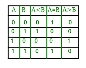
A single-bit comparator compares two individual bits. It has two inputs (one for each bit) and three outputs (less than, equal to, and greater than).
The truth table for a 1-bit comparator is as follows:
| A | B | A < B | A = B | A > B |
|---|---|---|---|---|
| 0 | 0 | 0 | 1 | 0 |
| 0 | 1 | 1 | 0 | 0 |
| 1 | 0 | 0 | 0 | 1 |
| 1 | 1 | 0 | 1 | 0 |
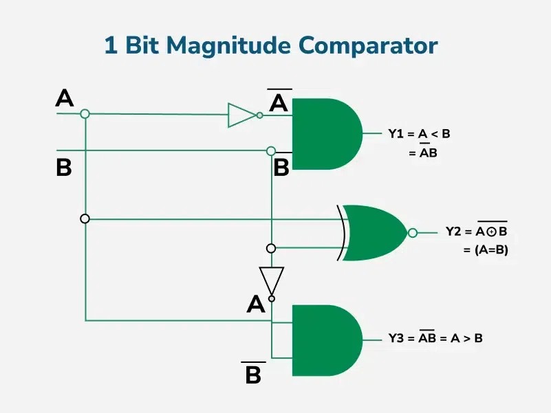
The logical expressions for each output are:
- A > B: A * B’
- A < B: A’ * B
- A = B: A’B’ + AB
Using these Boolean expressions, the logic circuit for a 1-bit comparator can be implemented.
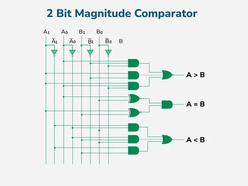
2.2 2-Bit Magnitude Comparator
A 2-bit magnitude comparator compares two 2-bit binary numbers. It consists of four inputs (two for each number) and three outputs (less than, equal to, and greater than).
The truth table for a 2-bit comparator is:
| A1 | A0 | B1 | B0 | A < B | A = B | A > B |
|---|---|---|---|---|---|---|
| 0 | 0 | 0 | 0 | 0 | 1 | 0 |
| 0 | 0 | 0 | 1 | 1 | 0 | 0 |
| 0 | 0 | 1 | 0 | 1 | 0 | 0 |
| 0 | 0 | 1 | 1 | 1 | 0 | 0 |
| 0 | 1 | 0 | 0 | 0 | 0 | 1 |
| 0 | 1 | 0 | 1 | 0 | 1 | 0 |
| 0 | 1 | 1 | 0 | 1 | 0 | 0 |
| 0 | 1 | 1 | 1 | 1 | 0 | 0 |
| 1 | 0 | 0 | 0 | 0 | 0 | 1 |
| 1 | 0 | 0 | 1 | 0 | 0 | 1 |
| 1 | 0 | 1 | 0 | 0 | 1 | 0 |
| 1 | 0 | 1 | 1 | 1 | 0 | 0 |
| 1 | 1 | 0 | 0 | 0 | 0 | 1 |
| 1 | 1 | 0 | 1 | 0 | 0 | 1 |
| 1 | 1 | 1 | 0 | 0 | 0 | 1 |
| 1 | 1 | 1 | 1 | 0 | 1 | 0 |
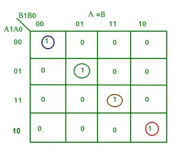
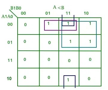
K-maps for each output can be derived from the truth table.
Truth Table of Output A > B
Truth Table of Output A = B
Truth Table of Output A < B
From the K-maps, the logical expressions for each output are:
- A > B: A1B1’ + A0B1’B0’ + A1A0B0’
- A = B: (A0 Ex-Nor B0) (A1 Ex-Nor B1)
- A < B: A1’B1 + A1’A0’B0 + A0’B1B0
Using these Boolean expressions, a logic circuit for the 2-bit comparator can be implemented.
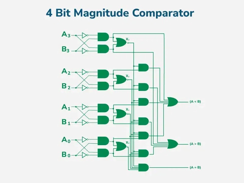
2.3 4-Bit Magnitude Comparator
A 4-bit magnitude comparator compares two 4-bit binary numbers. It has eight inputs (four for each number) and three outputs (less than, equal to, and greater than).
In a 4-bit comparator, A > B is true under these conditions:
- A3 = 1 and B3 = 0
- A3 = B3 and A2 = 1 and B2 = 0
- A3 = B3, A2 = B2 and A1 = 1 and B1 = 0
- A3 = B3, A2 = B2, A1 = B1 and A0 = 1 and B0 = 0
Similarly, A < B is true under these conditions:
- A3 = 0 and B3 = 1
- A3 = B3 and A2 = 0 and B2 = 1
- A3 = B3, A2 = B2 and A1 = 0 and B1 = 1
- A3 = B3, A2 = B2, A1 = B1 and A0 = 0 and B0 = 1
A = B is true only when all individual bits of one number exactly match the corresponding bits of the other number.
From the above statements, the logical expressions for each output are:
- A > B: A3B3’ + (A3 Ex-Nor B3)A2B2’ + (A3 Ex-Nor B3)(A2 Ex-Nor B2)A1B1’ + (A3 Ex-Nor B3)(A2 Ex-Nor B2)(A1 Ex-Nor B1)A0B0’
- A < B: A3’B3 + (A3 Ex-Nor B3)A2’B2 + (A3 Ex-Nor B3)(A2 Ex-Nor B2)A1’B1 + (A3 Ex-Nor B3)(A2 Ex-Nor B2)(A1 Ex-Nor B1)A0’B0
- A = B: (A3 Ex-Nor B3) (A2 Ex-Nor B2) (A1 Ex-Nor B1) (A0 Ex-Nor B0)
Using these Boolean expressions, a logic circuit for this comparator can be implemented.
For an n-bit comparator:
- Total combinations = 2^(2n)
- Equal combinations (A = B) = 2^n
- Unequal combinations = 2^(2n) – 2^n
- Greater (A > B) = Less (A < B) = (2^(2n) – 2^n) / 2
3. Cascading Comparators
3.1 Expanding Comparison Capabilities
To compare binary numbers with more than four bits, two or more 4-bit comparators can be cascaded. In cascading, the outputs of the lower-order comparator are connected to the corresponding inputs of the higher-order comparator. This setup allows for the comparison of larger binary numbers by combining multiple comparators.
3.2 Logic Behind Cascading
When cascading comparators, the A = B output of the lower-order comparator is connected to the enable input of the higher-order comparator. This ensures that the higher-order comparator is only enabled if the lower-order bits are equal. The A > B and A < B outputs of the cascaded comparators are determined by considering both the individual comparator outputs and the cascading logic.
4. Practical Applications of Digital Comparators
4.1 Use in Central Processing Units (CPUs) and Microcontrollers (MCUs)
Digital comparators are integral to CPUs and MCUs, where they are used for decision-making processes. They compare addresses, data values, and control signals to execute instructions and manage data flow.
4.2 Control Applications
Comparators are used in control applications to compare physical variables (such as temperature or position) represented as binary numbers with a reference value. This comparison is used to generate control signals that maintain the system at the desired state.
4.3 Process Controllers
In process control, comparators help maintain precise control over industrial processes by comparing process variables to set points. They generate error signals that drive control elements to correct any deviations.
4.4 Servo Motor Control
Comparators play a crucial role in servo motor control systems by comparing the desired position with the actual position of the motor. The comparator’s output is used to drive the motor until it reaches the desired position.
4.5 Password Verification and Biometric Applications
Comparators are used in password verification systems to compare the entered password with the stored password. Similarly, in biometric applications, comparators are used to compare biometric data (such as fingerprints) with stored templates for authentication purposes.
5. Advantages and Disadvantages of Digital Comparators
5.1 Advantages
- Simplicity and Efficiency: Comparators provide a straightforward and efficient means of comparing binary values.
- Fast Decision-Making: They enable rapid decision-making in digital circuits.
- Ease of Integration: Comparators can be easily integrated into complex systems like processors and arithmetic units.
- Modular Design: Their modular design allows them to scale for comparing multi-bit numbers.
5.2 Disadvantages
- Bit Limit: Comparators have a practical limit on the number of bits they can compare efficiently.
- Complexity for Large Bits: Complex circuits are required for comparing larger bit numbers.
- Power Consumption: Power consumption increases with the complexity of the circuit.
6. Digital Comparator vs Analog Comparator
6.1 Key Differences
Digital and analog comparators both serve the purpose of comparing signals, but they operate in fundamentally different domains and have distinct characteristics. The key differences are:
| Feature | Digital Comparator | Analog Comparator |
|---|---|---|
| Input Signals | Discrete, digital values (binary numbers) | Continuous, analog voltages |
| Output Signals | Discrete, digital values (typically HIGH or LOW) | Discrete, digital values (typically HIGH or LOW) |
| Comparison Type | Compares the magnitude of two digital numbers | Compares two analog voltages |
| Accuracy | Determined by the number of bits (quantization levels) | Limited by factors such as input offset voltage, noise, and propagation delay |
| Speed | Generally faster due to digital logic | Can be slower due to the need for signal amplification and settling |
| Applications | Digital systems, CPUs, microcontrollers, digital signal processing | Analog-to-digital converters (ADCs), zero-crossing detectors, level detectors |
6.2 Strengths and Weaknesses
Digital Comparator:
- Strengths:
- High accuracy, determined by the number of bits
- Fast operation
- Easy integration with digital systems
- Weaknesses:
- Requires analog signals to be converted to digital
- Can be more complex for large bit widths
Analog Comparator:
- Strengths:
- Direct comparison of analog signals
- Simple implementation
- Weaknesses:
- Lower accuracy due to analog imperfections
- Slower operation
- Sensitive to noise and interference
6.3 Practical Examples
Digital Comparator:
- CPU Address Decoding: Comparing memory addresses to determine which memory location to access.
- Microcontroller Peripherals: Comparing counter values in timers to trigger events.
- Digital Signal Processing: Comparing signal magnitudes in digital filters.
Analog Comparator:
- Analog-to-Digital Converters (ADCs): Comparing an analog input voltage to a series of reference voltages to generate a digital output.
- Zero-Crossing Detectors: Detecting when an AC signal crosses zero volts.
- Level Detectors: Detecting when an analog voltage exceeds a certain threshold.
7. Different Types of Digital Comparator ICs
7.1 Overview
Integrated circuits (ICs) for digital comparators come in various forms, each designed to meet specific needs in digital systems. These ICs vary in bit width, speed, and additional features. Here are some common types:
| IC Type | Description | Key Features |
|---|---|---|
| 4-Bit Comparators | Compares two 4-bit binary numbers | Common examples include the 74LS85 and CD4085. They typically provide A>B, A A=B outputs can be cascaded using additional inputs. |
| 8-Bit Comparators | Compares two 8-bit binary numbers | Offers a wider comparison range in a single IC. |
| Expandable Comparators | Designed to be cascaded for comparing larger bit widths | Include cascade inputs and outputs, allowing multiple ICs to be connected together to compare wider binary numbers. |
| High-Speed Comparators | Optimized for fast comparison operations | Typically use advanced logic families (e.g., ECL, advanced CMOS) to achieve higher speeds. |
| Low-Power Comparators | Designed for low power consumption | Ideal for battery-powered devices and applications where energy efficiency is critical. |
| Programmable Comparators | Allow configuration of comparison parameters through software or hardware | Can be configured to compare different bit widths, use different comparison algorithms, or provide additional features such as hysteresis or adjustable thresholds. |
7.2 Practical Examples
-
74LS85 (4-Bit Magnitude Comparator):
- Description: A widely used 4-bit magnitude comparator from the 74LS series.
- Key Features: Provides A>B, A=B, and A A=B can be cascaded.
-
CD4085 (4-Bit Magnitude Comparator):
- Description: A 4-bit magnitude comparator from the CD4000 series, known for its low power consumption.
- Key Features: Operates over a wide voltage range, suitable for various applications. Provides A>B, A=B, and A A=B outputs.
-
MC14585B (4-Bit Magnitude Comparator):
- Description: A 4-bit magnitude comparator with cascading capabilities.
- Key Features: Designed for easy expansion to compare larger bit widths. Provides A>B, A=B, and A
8. How to Select the Right Digital Comparator for Your Project
8.1 Project Requirements
Choosing the right digital comparator for a project involves carefully considering the project’s specific needs. Key factors include bit width, speed, power consumption, and cost.
8.2 Bit Width
Bit width refers to the number of bits that the comparator can compare simultaneously. Select a comparator with a bit width that matches the size of the binary numbers being compared. If you need to compare larger numbers, consider using expandable comparators that can be cascaded.
8.3 Speed
Speed is the time it takes for the comparator to produce a valid output after the inputs change. High-speed comparators are necessary for applications that require fast decision-making, such as high-frequency digital signal processing.
8.4 Power Consumption
Power consumption is the amount of power the comparator consumes during operation. Low-power comparators are ideal for battery-powered devices and applications where energy efficiency is important.
8.5 Cost
Cost is always a consideration when selecting components. Comparators vary in price depending on their features and performance. Evaluate the trade-offs between cost and performance to choose the most appropriate comparator for your budget.
9. Common Challenges and Solutions When Using Digital Comparators
9.1 Noise and Signal Integrity
Noise and signal integrity issues can affect the accuracy and reliability of digital comparators. Common symptoms include erratic or incorrect comparisons. Solutions include:
- Proper Grounding: Ensure a stable and low-impedance ground connection to minimize ground bounce and noise.
- Bypass Capacitors: Use bypass capacitors near the comparator’s power supply pins to filter out high-frequency noise.
- Shielded Cables: Use shielded cables for input signals to reduce electromagnetic interference (EMI).
- Signal Filtering: Implement low-pass filters on input signals to attenuate high-frequency noise.
9.2 Propagation Delay
Propagation delay is the time it takes for the comparator’s output to respond to changes in the input signals. Excessive propagation delay can limit the speed and performance of the system. Solutions include:
- Faster Comparators: Choose comparators with lower propagation delay specifications.
- Clock Synchronization: Synchronize the input signals and clock signals to minimize timing skew.
- Look-Ahead Techniques: Implement look-ahead techniques to anticipate the comparison result and reduce delay.
9.3 Metastability
Metastability can occur when the comparator’s input signals change close to the clock edge, causing the output to enter an undefined state. Solutions include:
- Synchronizers: Use synchronizers to ensure that the input signals meet the setup and hold time requirements of the comparator.
- Metastability-Hardened Comparators: Choose comparators that are designed to minimize the risk of metastability.
- Output Latches: Use output latches to capture the comparator’s output and prevent it from changing during metastable states.
10. Advanced Techniques and Innovations in Digital Comparators
10.1 High-Speed Comparators
High-speed comparators are designed to operate at very high frequencies, enabling fast decision-making in demanding applications. These comparators typically use advanced logic families such as ECL or advanced CMOS to achieve higher speeds. Innovations include:
- Reduced Transistor Size: Smaller transistor sizes reduce parasitic capacitances and improve switching speed.
- Optimized Layout: Careful layout design minimizes signal path lengths and reduces signal propagation delay.
- Advanced Compensation Techniques: Compensation techniques such as Miller compensation are used to improve stability and bandwidth.
10.2 Low-Power Comparators
Low-power comparators are designed to minimize power consumption, making them ideal for battery-powered devices and energy-efficient applications. Innovations include:
- Adaptive Biasing: Adaptive biasing techniques adjust the comparator’s bias current based on the input signal conditions, reducing power consumption during idle periods.
- Power Gating: Power gating techniques selectively disable portions of the comparator circuit when they are not needed, further reducing power consumption.
- Subthreshold Operation: Operating transistors in the subthreshold region reduces power consumption but requires careful design to maintain performance.
10.3 Programmable Comparators
Programmable comparators allow you to configure comparison parameters through software or hardware, providing flexibility and adaptability in various applications. Innovations include:
- Adjustable Thresholds: Programmable comparators can be configured to compare different bit widths, use different comparison algorithms, or provide additional features such as hysteresis or adjustable thresholds.
- Hysteresis Control: Hysteresis control prevents oscillations and improves noise immunity by introducing a small difference between the rising and falling thresholds.
- Multiple Comparison Modes: Some programmable comparators offer multiple comparison modes, such as window comparison or absolute value comparison, to support a wider range of applications.
11. Future Trends in Digital Comparator Technology
11.1 Integration with AI and Machine Learning
Future digital comparators may be integrated with AI and machine learning algorithms to enable more intelligent decision-making in digital systems. For example, AI-powered comparators could be used to adaptively adjust comparison thresholds based on real-time data, improving accuracy and performance.
11.2 Enhanced Security Features
As digital systems become more vulnerable to security threats, future digital comparators may incorporate enhanced security features such as encryption and authentication. These features could protect against tampering and unauthorized access, ensuring the integrity and confidentiality of sensitive data.
11.3 3D Integration
3D integration techniques, such as stacking multiple comparator dies on top of each other, could enable higher density and performance in digital comparator designs. 3D integration could also reduce power consumption and improve signal integrity by minimizing interconnect lengths.
12. Digital Comparator Case Studies
12.1 Case Study 1: High-Speed Data Acquisition System
- Application: A high-speed data acquisition system for capturing and processing analog signals.
- Challenge: The system requires fast and accurate comparison of analog signals to trigger data acquisition events.
- Solution: A high-speed comparator with low propagation delay is used to compare the input signal with a reference voltage. The comparator’s output triggers an analog-to-digital converter (ADC) to capture the data.
12.2 Case Study 2: Battery-Powered IoT Device
- Application: A battery-powered IoT device for monitoring environmental conditions.
- Challenge: The device needs to operate for extended periods on a single battery charge.
- Solution: A low-power comparator is used to compare sensor readings with predefined thresholds. The comparator’s output triggers an alert or activates a power-saving mode to conserve energy.
12.3 Case Study 3: Industrial Control System
- Application: An industrial control system for regulating temperature in a chemical reactor.
- Challenge: The system requires precise and reliable temperature control to ensure product quality and safety.
- Solution: A programmable comparator with adjustable thresholds is used to compare the reactor temperature with a setpoint. The comparator’s output drives a control valve to adjust the heating or cooling rate.
13. Maintaining and Troubleshooting Digital Comparators
13.1 Regular Checks and Maintenance
Maintaining digital comparators involves regular checks and maintenance to ensure they operate correctly and reliably. Here are some essential maintenance tasks:
- Visual Inspection: Check for physical damage, such as cracks, bent pins, or signs of overheating.
- Power Supply Verification: Ensure the power supply voltage is within the specified range and is stable.
- Signal Integrity Checks: Verify that input and output signals are clean and free from excessive noise or distortion.
13.2 Troubleshooting Techniques
When digital comparators malfunction, systematic troubleshooting is necessary to identify and resolve the issue. Here are some common troubleshooting techniques:
- Signal Tracing: Use an oscilloscope or logic analyzer to trace signals through the comparator circuit and identify any points where the signal is lost or distorted.
- Component Testing: Test individual components, such as resistors, capacitors, and transistors, to ensure they are functioning correctly.
- Substitution: Replace the comparator with a known good unit to see if the problem is resolved.
13.3 Common Problems and Solutions
-
Incorrect Output:
- Problem: The comparator’s output is incorrect or erratic.
- Solution: Check input signal levels, verify power supply voltage, and ensure proper grounding.
-
Slow Response Time:
- Problem: The comparator’s response time is slower than expected.
- Solution: Use a faster comparator, reduce load capacitance, and optimize signal routing.
-
Oscillations:
- Problem: The comparator’s output oscillates or exhibits instability.
- Solution: Add hysteresis to the comparator, use bypass capacitors, and shield signal cables.
14. Frequently Asked Questions (FAQs) About Digital Comparators
1. What is a digital comparator?
A digital comparator is a combinational logic circuit that compares two digital inputs and outputs signals indicating whether one input is greater than, less than, or equal to the other.
2. How does a digital comparator work?
A digital comparator works by comparing the individual bits of the two input numbers, starting from the most significant bit (MSB). It uses logic gates to determine the relationship between the two numbers.
3. What are the different types of digital comparators?
The main types of digital comparators are 1-bit, 2-bit, and 4-bit comparators. Larger bit-width comparators can be created by cascading multiple smaller comparators.
4. What are the applications of digital comparators?
Digital comparators are used in CPUs, microcontrollers, process control systems, servo motor control, password verification, and biometric applications.
5. What are the advantages of using digital comparators?
Advantages include simplicity, efficiency, fast decision-making, ease of integration, and modular design.
6. What are the disadvantages of using digital comparators?
Disadvantages include bit limits, complexity for larger bits, and increased power consumption with circuit complexity.
7. How do I select the right digital comparator for my project?
Consider the bit width, speed, power consumption, and cost requirements of your project.
8. How can I troubleshoot common problems with digital comparators?
Use techniques such as signal tracing, component testing, and substitution to identify and resolve issues.
9. What are some advanced techniques in digital comparator technology?
Advanced techniques include high-speed comparators, low-power comparators, and programmable comparators.
10. What are the future trends in digital comparator technology?
Future trends include integration with AI, enhanced security features, and 3D integration.
15. Real-World Digital Comparator Examples
15.1 Industrial Automation
In industrial automation, digital comparators are used to monitor and control various processes. For instance, they can compare the output of a temperature sensor with a predefined threshold to trigger an alarm or activate a cooling system. This ensures that the temperature remains within a safe and optimal range.
15.2 Automotive Systems
Digital comparators are essential in automotive systems for various functions. They can compare the speed of the wheels to detect wheel slippage, which is crucial for anti-lock braking systems (ABS). Additionally, they can compare the throttle position sensor (TPS) output with a reference voltage to control the fuel injection system.
15.3 Medical Devices
In medical devices, digital comparators ensure accurate and reliable operation. They can compare the output of a blood glucose sensor with a safe range to alert the patient or administer insulin. Additionally, they can monitor heart rate and blood pressure, triggering alarms if the readings fall outside acceptable limits.
15.4 Consumer Electronics
Digital comparators play a role in various consumer electronics. They can compare the volume level of an audio system with a maximum threshold to prevent damage to the speakers. Additionally, they can compare the brightness level of a display with ambient light conditions to automatically adjust the screen brightness.
16. Digital Comparator Manufacturers
16.1 Renowned Companies
Many companies manufacture digital comparators, each offering different features and specifications. Here are some of the well-known companies:
- Texas Instruments (TI): Known for a wide range of digital comparators with high performance and reliability.
- Analog Devices (ADI): Offers precision comparators designed for accuracy and low power consumption.
- STMicroelectronics (STM): Provides a variety of comparators for various applications, including industrial and automotive.
- ON Semiconductor: Specializes in comparators for power management and automotive applications.
- Microchip Technology: Offers comparators integrated into microcontrollers and other embedded systems.
16.2 Choosing a Manufacturer
When selecting a digital comparator manufacturer, consider factors such as:
- Product Range: Choose a manufacturer that offers a range of comparators to meet your specific needs.
- Performance: Evaluate the comparator’s speed, accuracy, and power consumption.
- Reliability: Look for manufacturers with a reputation for high-quality and reliable products.
- Support: Ensure the manufacturer provides adequate technical support and documentation.
17. Resources for Learning More About Digital Comparators
17.1 Online Platforms
Various online resources can help you learn more about digital comparators:
- COMPARE.EDU.VN: Offers comprehensive comparisons and detailed analyses of digital comparators, helping you understand their functionality and applications.
- Electronics Tutorials: Provides detailed explanations of digital comparator circuits and their operation.
- All About Circuits: Features articles and tutorials on digital logic and comparators.
- YouTube: Offers video tutorials and demonstrations of digital comparator circuits.
- Textbooks: Provides in-depth coverage of digital comparators and related topics.
17.2 Experimentation
Experimenting with digital comparator circuits is an effective way to gain hands-on experience. You can build and test comparator circuits using breadboards, logic gates, and other electronic components.
18. The Role of COMPARE.EDU.VN
At COMPARE.EDU.VN, we understand the challenges in comparing different digital comparators to find the perfect fit for your specific needs. Our website offers detailed, objective comparisons across various brands, bit widths, and functionalities. Whether you are a student, a consumer, or a seasoned professional, COMPARE.EDU.VN provides the insights you need to make informed decisions.
Ready to make a smart decision? Visit COMPARE.EDU.VN today to explore comprehensive comparisons, detailed reviews, and expert insights. Let us help you find the perfect digital comparator for your project.
Address: 333 Comparison Plaza, Choice City, CA 90210, United States
WhatsApp: +1 (626) 555-9090
Website: compare.edu.vn