How Can Electricity Be Compared To Water? This is a common question, and at COMPARE.EDU.VN, we provide a clear, intuitive analogy by comparing electrical concepts to water flow. Understanding this comparison makes grasping complex electrical principles easier and allows for better decision-making regarding energy use and technological applications. Dive in to explore the fascinating parallels between electrical and fluid dynamics.
1. The Core Analogy: Electricity as Water Flow
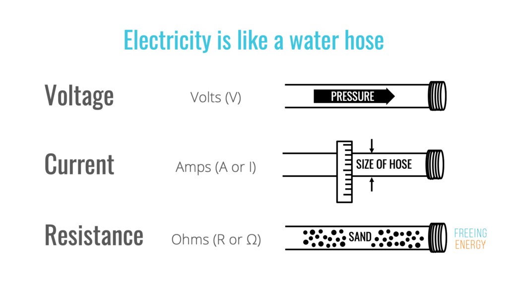
The comparison of electricity to water flow is a powerful tool for understanding the fundamentals of electrical circuits. At its core, this analogy relies on mapping the key components of electrical systems – voltage, current, and resistance – onto analogous properties of water flowing through a pipe. Let’s break down these components and their water-based counterparts:
- Voltage (Electrical Potential): Voltage is the driving force behind electrical current. It represents the potential difference that pushes electrons through a circuit. Think of it as the water pressure in a pipe. A higher water pressure (higher voltage) will push more water (more current) through the pipe.
- Current (Electrical Flow): Current is the rate at which electric charge flows through a circuit. It’s measured in amperes (amps). In the water analogy, current is the amount of water flowing through the pipe per unit of time. A larger current means more water is flowing.
- Resistance (Opposition to Flow): Resistance opposes the flow of electric current. It’s measured in ohms. Imagine placing a narrow constriction or obstacle inside the pipe. This would restrict the flow of water, acting as resistance. A higher resistance means less current (water) will flow for a given voltage (pressure).
This analogy helps to visualize the behavior of electrical circuits. For example, Ohm’s Law, which states that Voltage (V) = Current (I) * Resistance (R), can be easily understood in terms of water flow. If you increase the water pressure (voltage) while keeping the resistance (pipe constriction) constant, the flow rate (current) will increase. Conversely, if you increase the resistance while keeping the pressure constant, the flow rate will decrease.
Understanding this basic analogy lays the groundwork for comprehending more complex electrical concepts. It allows individuals, even without a strong technical background, to develop an intuition for how electrical circuits behave and how different components interact. COMPARE.EDU.VN utilizes this analogy to help users make informed comparisons of various electrical devices and systems.
2. Voltage vs. Water Pressure: The Driving Force
Voltage is often described as the “electrical pressure” that drives the flow of current through a circuit. This is directly analogous to water pressure in a plumbing system. The higher the water pressure, the more forcefully water will flow through the pipes. Similarly, the higher the voltage, the more forcefully electrons will flow through the circuit.
Here’s a detailed breakdown of the parallels:
| Feature | Voltage (Electricity) | Water Pressure (Water) |
|---|---|---|
| Definition | Electrical potential difference, measured in volts (V) | Force per unit area, measured in pascals (Pa) or PSI |
| Role | Drives the flow of current | Drives the flow of water |
| Impact of Increase | Higher voltage leads to greater current (given constant resistance) | Higher pressure leads to greater flow (given constant resistance) |
| Source | Batteries, generators, power supplies | Pumps, gravity, water towers |
Consider a simple circuit with a battery and a light bulb. The battery provides the voltage, which pushes the electrons through the circuit and into the light bulb, causing it to light up. If you increase the voltage of the battery, the light bulb will shine brighter because more current is flowing through it. Similarly, if you increase the water pressure in a pipe connected to a sprinkler, the sprinkler will spray water with more force.
The concept of voltage drop is also analogous to pressure drop in water systems. As water flows through a long pipe or encounters resistance, the pressure decreases due to friction. Similarly, as current flows through a resistor in an electrical circuit, the voltage decreases.
Understanding the relationship between voltage and water pressure is crucial for troubleshooting electrical problems. For instance, if a light bulb is dim, it could be due to low voltage in the circuit, just as weak water flow from a faucet could be due to low water pressure. COMPARE.EDU.VN provides tools and comparisons to help users identify and address such issues effectively.
3. Current vs. Water Flow Rate: The Quantity
While voltage represents the “push” behind electrical current, current itself is the measure of how much charge is flowing. In the water analogy, current is analogous to the flow rate of water – the volume of water passing a certain point per unit of time. Current is measured in amperes (amps), while water flow rate is typically measured in gallons per minute (GPM) or liters per second (L/s).
Here’s a comparison table highlighting the similarities:
| Feature | Current (Electricity) | Water Flow Rate (Water) |
|---|---|---|
| Definition | Rate of flow of electric charge, measured in amps (A) | Volume of water passing a point per unit time (GPM/LPS) |
| Role | Represents the quantity of electrical flow | Represents the quantity of water flow |
| Impact of Increase | Higher current allows for more work to be done | Higher flow rate allows for more water to be delivered |
| Measurement | Ammeter | Flow meter |
Imagine a garden hose. The amount of water flowing out of the hose depends on the water pressure (voltage) and the diameter of the hose (related to resistance). If you open the faucet wider (increase voltage), the flow rate (current) will increase. Similarly, if you replace the hose with a wider one (decrease resistance), the flow rate will also increase.
In an electrical circuit, a higher current means more electrons are flowing, which can deliver more power to a load, such as a motor or a heater. However, excessive current can also overload a circuit and cause damage, just as excessive water flow can burst a pipe.
Understanding current is essential for selecting the right size wires and circuit breakers for electrical systems. Wires have a maximum current carrying capacity, and exceeding this limit can cause them to overheat and potentially start a fire. COMPARE.EDU.VN offers comparisons of different electrical components, including their current ratings, to help users make safe and informed choices.
4. Resistance vs. Pipe Diameter/Obstructions: Impeding the Flow
Resistance is the opposition to the flow of electrical current. It’s measured in ohms (Ω). In the water analogy, resistance is similar to the diameter of a pipe or any obstructions that impede the flow of water. A narrower pipe or an obstruction will create more resistance, reducing the flow rate for a given pressure.
The following table illustrates this comparison:
| Feature | Resistance (Electricity) | Pipe Diameter/Obstructions (Water) |
|---|---|---|
| Definition | Opposition to the flow of electric current, measured in ohms (Ω) | Restriction to water flow due to pipe size/obstacles |
| Role | Limits the amount of current flowing in a circuit | Limits the amount of water flowing in a pipe |
| Impact of Increase | Higher resistance leads to lower current (given constant voltage) | Narrower pipe/obstruction leads to lower flow rate (constant pressure) |
| Examples | Resistors, long wires | Narrow pipes, partially closed valves, sediment buildup |
Consider a simple electrical circuit with a resistor connected to a battery. The resistor limits the amount of current that can flow through the circuit. A higher resistance value will result in a lower current flow. Similarly, if you squeeze a garden hose, you are increasing the resistance to water flow, which reduces the amount of water that comes out.
The concept of resistance is crucial for controlling the flow of current in electrical circuits. Resistors are used to limit current, divide voltage, and create timing circuits. In water systems, valves and regulators are used to control water flow and pressure.
Understanding resistance helps in troubleshooting electrical problems. For example, if a device is not working properly, it could be due to a high resistance connection, just as a clogged pipe can restrict water flow. COMPARE.EDU.VN provides comparisons of different resistors and their applications, helping users select the right components for their projects.
5. Circuits vs. Plumbing Systems: Complete Pathways
An electrical circuit is a complete path through which electric current can flow. It typically consists of a voltage source (like a battery), conductors (wires), and a load (like a light bulb or motor). Similarly, a plumbing system is a complete network of pipes and fixtures through which water can flow, typically consisting of a water source, pipes, and outlets (like faucets or showerheads).
Here’s a comparison of the key elements:
| Feature | Electrical Circuit | Plumbing System |
|---|---|---|
| Components | Voltage source (battery), conductors (wires), load (bulb) | Water source, pipes, outlets (faucets) |
| Flow | Electric current flows in a closed loop | Water flows in a closed loop (in closed-loop systems) |
| Purpose | To provide power to a load | To deliver water to desired locations |
| Interruptions | Breaks in the circuit stop current flow | Leaks or blockages stop water flow |
In an electrical circuit, the current flows from the voltage source, through the conductors, to the load, and back to the voltage source. If there is a break in the circuit, such as a broken wire, the current will stop flowing, and the load will not function. Similarly, in a plumbing system, the water flows from the water source, through the pipes, to the outlets. If there is a leak or blockage in the pipes, the water flow will be disrupted.
The concept of series and parallel circuits can also be understood using the plumbing analogy. In a series circuit, components are connected one after another, so the same current flows through each component. This is analogous to a series of pipes connected end-to-end, where the same amount of water flows through each pipe. In a parallel circuit, components are connected side-by-side, so the current is divided among the components. This is analogous to a system of parallel pipes, where the water flow is divided among the pipes.
Understanding the concept of circuits and plumbing systems is crucial for designing and troubleshooting both electrical and plumbing installations. COMPARE.EDU.VN offers comparisons of different circuit configurations and plumbing layouts, helping users make informed decisions about their projects.
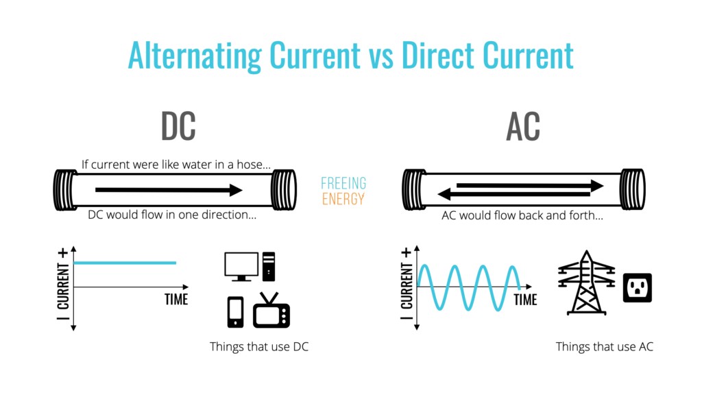
6. Direct Current (DC) vs. Steady Water Flow
Direct current (DC) is a type of electrical current that flows in one direction only. This is analogous to a steady, continuous flow of water in a pipe. Batteries are a common source of DC power, providing a constant voltage that drives the current in one direction.
Here’s a simple comparison:
| Feature | Direct Current (DC) | Steady Water Flow |
|---|---|---|
| Direction | Flows in one direction only | Flows in one direction only |
| Source | Batteries, DC power supplies | Pumps, elevated water tanks |
| Application | Electronics, battery-powered devices | Continuous water supply, irrigation systems |
| Analogy | Constant pressure pushing water in a single direction | Pump maintaining steady pressure and flow rate |
Imagine a pump continuously pushing water through a pipe at a constant rate. This is similar to how a battery provides a constant voltage that drives a DC current through a circuit. The current flows from the positive terminal of the battery, through the circuit, to the negative terminal, and back to the battery.
DC power is commonly used in electronic devices, such as cell phones, laptops, and other battery-powered devices. These devices require a constant voltage to operate properly, which is why they use DC power.
The concept of DC voltage and current is essential for understanding how electronic devices work. COMPARE.EDU.VN offers comparisons of different DC power supplies and their applications, helping users select the right power supply for their needs.
7. Alternating Current (AC) vs. Oscillating Water Flow
Alternating current (AC) is a type of electrical current that periodically reverses direction. This is analogous to water flowing back and forth in a pipe. The water doesn’t move in a continuous stream but oscillates, changing direction at a specific frequency.
Here’s a detailed comparison:
| Feature | Alternating Current (AC) | Oscillating Water Flow |
|---|---|---|
| Direction | Periodically reverses direction | Periodically reverses direction |
| Frequency | Measured in Hertz (Hz), cycles per second | Cycles per second |
| Source | Generators, AC power supplies | Oscillating pumps, reciprocating mechanisms |
| Application | Powering homes and businesses, electric motors | Wave pools, reciprocating water systems |
| Water Analogy | A pump that reverses its direction, pushing water back and forth | A piston moving back and forth in a cylinder, creating oscillation |
Imagine a pump that periodically reverses its direction, pushing water back and forth in a pipe. This is similar to how an AC generator produces an alternating voltage that drives an AC current through a circuit. The current flows in one direction for a short period, then reverses and flows in the opposite direction.
AC power is the standard form of electricity used in homes and businesses. It is generated by power plants and transmitted over long distances using high-voltage transmission lines. Transformers are used to step up or step down the voltage of AC power, making it suitable for different applications.
While the water analogy for AC is less direct than for DC, it helps to visualize the changing direction of current flow. COMPARE.EDU.VN offers comparisons of different AC power sources and their applications, helping users understand the benefits and limitations of AC power.
8. Batteries vs. Water Reservoirs with Pumps
Batteries store electrical energy and release it as direct current (DC). In the water analogy, batteries can be compared to water reservoirs equipped with pumps. The reservoir stores a quantity of water, and the pump provides the pressure to push the water through pipes.
Here’s a table comparing the functions:
| Feature | Batteries (Electricity) | Water Reservoirs with Pumps (Water) |
|---|---|---|
| Function | Store electrical energy and release as DC | Store water and provide pressure to deliver water |
| Components | Chemical cells, electrodes | Tank, pump, pipes |
| Output | Voltage and current | Water pressure and flow rate |
| Recharge | Reversible chemical reaction | Refilling the reservoir |
| Water Analogy | A contained source of energy that can be released on demand | A stored water supply that can be delivered when needed |
A battery provides a constant voltage, which drives the current through the circuit. The amount of energy stored in a battery is measured in amp-hours (Ah) or kilowatt-hours (kWh). Similarly, a water reservoir stores a certain volume of water, which can be released at a specific flow rate.
Just as batteries need to be recharged after they are depleted, water reservoirs need to be refilled after they are emptied. The capacity of a battery is analogous to the size of the water reservoir, and the voltage of the battery is analogous to the water pressure provided by the pump.
Batteries are used in a wide range of applications, from powering small electronic devices to storing energy from renewable sources like solar and wind. COMPARE.EDU.VN provides comparisons of different battery types and their applications, helping users select the best battery for their needs.
9. Transformers vs. Nozzles: Changing Pressure and Flow
Transformers are devices that increase or decrease the voltage of alternating current (AC) power. In the water analogy, transformers can be compared to nozzles on a garden hose. By adjusting the nozzle, you can change the water pressure and flow rate.
Here’s a detailed comparison:
| Feature | Transformers (Electricity) | Nozzles (Water) |
|---|---|---|
| Function | Increase or decrease AC voltage | Change water pressure and flow rate |
| Principle | Electromagnetic induction | Adjusting the opening size |
| Input/Output | High voltage, low current to low voltage, high current (or vice versa) | High pressure, low flow to low pressure, high flow (or vice versa) |
| Water Analogy | An adjustable device that alters the electrical properties | An adjustable device that alters the water properties |
Transformers work by transferring electrical energy from one circuit to another through electromagnetic induction. They consist of two or more coils of wire wound around a common core. The ratio of the number of turns in the coils determines the voltage transformation ratio.
Similarly, a nozzle on a garden hose changes the water pressure and flow rate by adjusting the size of the opening. When the opening is narrowed, the water pressure increases, and the flow rate decreases. When the opening is widened, the water pressure decreases, and the flow rate increases.
Transformers are essential components in power transmission systems, allowing electricity to be transmitted over long distances at high voltages and then stepped down to lower voltages for use in homes and businesses. COMPARE.EDU.VN offers comparisons of different transformer types and their applications, helping users understand how transformers work and how they are used in electrical systems.
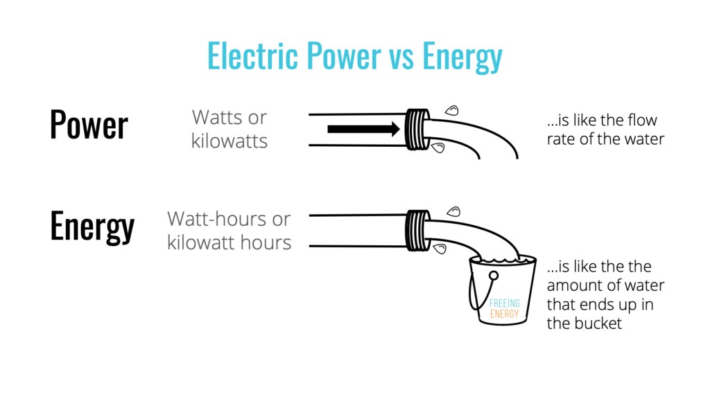
10. Power vs. Water Flow Rate Under Pressure
In electrical terms, power is the rate at which electrical energy is transferred or used. It’s measured in watts (W). In the water analogy, power is analogous to the water flow rate under pressure. It’s the combination of how much water is flowing and how forcefully it’s flowing.
Here’s a comparison highlighting the key points:
| Feature | Power (Electricity) | Water Flow Rate Under Pressure (Water) |
|---|---|---|
| Definition | Rate of energy transfer, measured in watts (W) | Volume of water flowing per unit time under a specific pressure |
| Calculation | Voltage (V) * Current (I) | Pressure * Flow Rate |
| Impact of Increase | Higher power allows for more work to be done | Higher flow rate under pressure allows for more tasks to be accomplished |
| Application | Calculating energy consumption, sizing electrical components | Designing efficient water systems |
Power is calculated as the product of voltage and current (P = V * I). In the water analogy, power is related to both the water pressure and the flow rate. A higher water pressure and a higher flow rate will result in a higher power, meaning more work can be done.
For example, a high-pressure washer uses a high water pressure and a high flow rate to clean surfaces effectively. Similarly, a high-power electrical device uses a high voltage and a high current to perform its function.
Understanding power is essential for designing and operating electrical systems efficiently. COMPARE.EDU.VN offers comparisons of different electrical devices and their power consumption, helping users make informed decisions about energy usage.
11. Energy vs. Total Water Volume Delivered
Energy is the total amount of work that can be done. It’s measured in watt-hours (Wh) or kilowatt-hours (kWh). In the water analogy, energy is analogous to the total volume of water delivered over a period of time.
Here’s a comparison table outlining the similarities:
| Feature | Energy (Electricity) | Total Water Volume Delivered (Water) |
|---|---|---|
| Definition | Total work done or energy consumed, measured in kWh | Total volume of water delivered over a period of time |
| Calculation | Power (kW) * Time (hours) | Flow Rate * Time |
| Measurement | Kilowatt-hours (kWh) | Gallons or Liters |
| Application | Calculating electricity bills, energy consumption | Tracking water usage, irrigation planning |
Energy consumption is calculated as the product of power and time (E = P * t). For example, a 100-watt light bulb that is left on for 10 hours will consume 1000 watt-hours or 1 kWh of energy. Similarly, a water tap that flows at a rate of 1 gallon per minute for 10 minutes will deliver 10 gallons of water.
Energy is what you pay for on your electricity bill, just as you pay for the total volume of water you use on your water bill. Understanding energy consumption is essential for managing your energy costs and reducing your environmental impact. COMPARE.EDU.VN offers tools and comparisons to help users track their energy usage and identify ways to save energy.
12. Short Circuit vs. Burst Pipe: Uncontrolled Flow
A short circuit is an abnormal connection in an electrical circuit that allows current to flow through an unintended path with very little resistance. This results in a large, uncontrolled current flow, which can cause overheating, damage to equipment, and even fire. In the water analogy, a short circuit is similar to a burst pipe.
Here’s a comparative analysis:
| Feature | Short Circuit (Electricity) | Burst Pipe (Water) |
|---|---|---|
| Definition | Unintended path of low resistance, high current flow | Uncontrolled release of water due to pipe failure |
| Cause | Faulty wiring, insulation breakdown | Excessive pressure, corrosion, physical damage |
| Effect | Overheating, damage to equipment, fire hazard | Water damage, flooding, loss of water pressure |
| Prevention | Fuses, circuit breakers, proper insulation | Pressure regulators, durable pipes, regular maintenance |
| Water Analogy | An uncontrolled surge of electricity due to a fault | An uncontrolled surge of water due to pipe rupture |
In a short circuit, the current bypasses the intended load and flows directly back to the voltage source, creating a large current flow. This can cause the wires to overheat and melt, potentially starting a fire. Similarly, a burst pipe releases a large volume of water uncontrollably, causing water damage and flooding.
Fuses and circuit breakers are used to protect electrical circuits from short circuits by interrupting the current flow when it exceeds a safe level. Pressure regulators and durable pipes are used to prevent burst pipes by controlling the water pressure and ensuring the integrity of the plumbing system.
Understanding the dangers of short circuits and burst pipes is essential for maintaining safe and reliable electrical and plumbing systems. COMPARE.EDU.VN offers resources and comparisons to help users understand these hazards and take steps to prevent them.
13. Grounding vs. Drainage: Safety Mechanisms
Grounding in electrical systems is a safety measure that provides a low-resistance path for fault currents to flow back to the source, tripping a circuit breaker or fuse and preventing electrical shock. In the water analogy, grounding is similar to drainage in a plumbing system.
Here’s a detailed comparison:
| Feature | Grounding (Electricity) | Drainage (Water) |
|---|---|---|
| Function | Provides a low-resistance path for fault currents | Provides a path for excess water to be removed |
| Purpose | Protects against electrical shock | Prevents water damage, flooding |
| Mechanism | Ground wire, grounding rod | Drain pipes, sump pumps |
| Water Analogy | A safety valve that prevents electrical buildup | A safety valve that prevents water buildup |
Grounding ensures that if a fault occurs in an electrical device, the current will flow through the ground wire back to the source, rather than through a person who might touch the device. This trips the circuit breaker or fuse, cutting off the power and preventing electrical shock.
Similarly, drainage systems remove excess water from buildings, preventing water damage and flooding. Drain pipes carry wastewater away from sinks, toilets, and showers, and sump pumps remove water from basements.
Understanding the importance of grounding and drainage is essential for ensuring the safety and reliability of electrical and plumbing systems. COMPARE.EDU.VN offers resources and comparisons to help users understand these safety mechanisms and how they work.
14. Conductors vs. Pipes: Allowing Easy Flow
Conductors are materials that allow electric current to flow easily. Copper and aluminum are common conductors used in electrical wiring. In the water analogy, conductors are similar to pipes in a plumbing system.
Here’s a comparative analysis:
| Feature | Conductors (Electricity) | Pipes (Water) |
|---|---|---|
| Function | Allow electric current to flow easily | Allow water to flow easily |
| Material | Copper, aluminum | PVC, copper, steel |
| Property | Low resistance | Smooth interior, large diameter |
| Water Analogy | A pathway for electricity to travel | A pathway for water to travel |
Conductors have low electrical resistance, which means that they allow current to flow with minimal energy loss. Similarly, pipes have smooth interiors and large diameters, which minimize friction and allow water to flow easily.
The size of a conductor is important for determining how much current it can safely carry. Larger conductors can carry more current without overheating. Similarly, the diameter of a pipe is important for determining how much water it can carry without causing a pressure drop.
Understanding the properties of conductors and pipes is essential for designing efficient and reliable electrical and plumbing systems. COMPARE.EDU.VN offers comparisons of different conductors and pipes, helping users select the right materials for their projects.
15. Insulators vs. Pipe Insulation: Preventing Loss
Insulators are materials that prevent the flow of electric current. They are used to protect people from electrical shock and to prevent short circuits. In the water analogy, insulators are similar to pipe insulation.
Here’s a detailed comparison:
| Feature | Insulators (Electricity) | Pipe Insulation (Water) |
|---|---|---|
| Function | Prevent the flow of electric current | Prevent heat loss or gain from water in pipes |
| Material | Rubber, plastic, glass | Foam, fiberglass |
| Property | High resistance | Low thermal conductivity |
| Water Analogy | A barrier to electricity flow | A barrier to heat transfer in water systems |
Insulators have high electrical resistance, which means that they prevent current from flowing through them. Similarly, pipe insulation has low thermal conductivity, which means that it prevents heat from being lost or gained from the water in the pipes.
Insulators are used to coat electrical wires and components, preventing them from coming into contact with other objects or people. Pipe insulation is used to wrap around pipes, preventing heat loss in hot water pipes and preventing condensation in cold water pipes.
Understanding the properties of insulators and pipe insulation is essential for designing safe and energy-efficient electrical and plumbing systems. COMPARE.EDU.VN offers comparisons of different insulators and pipe insulation, helping users select the right materials for their projects.
16. Fuses and Circuit Breakers vs. Pressure Relief Valves
Fuses and circuit breakers are safety devices that protect electrical circuits from overcurrent. They interrupt the flow of current when it exceeds a safe level, preventing overheating and damage to equipment. In the water analogy, fuses and circuit breakers are similar to pressure relief valves in a plumbing system.
Here’s a comparison table outlining the similarities:
| Feature | Fuses and Circuit Breakers (Electricity) | Pressure Relief Valves (Water) |
|---|---|---|
| Function | Interrupt the flow of current when it exceeds a safe level | Release excess pressure to prevent damage |
| Purpose | Prevent overheating, damage to equipment, and fire hazard | Prevent pipe bursts, tank explosions |
| Mechanism | Melts a wire or trips a switch | Opens a valve |
| Water Analogy | A safeguard against electrical overload | A safeguard against water pressure overload |
Fuses contain a thin wire that melts and breaks the circuit when the current exceeds a certain level. Circuit breakers use a switch that trips and interrupts the circuit when the current exceeds a certain level. Both devices prevent overcurrent from damaging electrical equipment or starting a fire.
Pressure relief valves release excess pressure in a plumbing system, preventing pipe bursts and tank explosions. They open automatically when the pressure exceeds a safe level, releasing water until the pressure drops back to normal.
Understanding the function of fuses, circuit breakers, and pressure relief valves is essential for maintaining safe and reliable electrical and plumbing systems. COMPARE.EDU.VN offers resources and comparisons to help users understand these safety devices and how they work.
17. Ground Fault Circuit Interrupters (GFCIs) vs. Overflow Drains
Ground Fault Circuit Interrupters (GFCIs) are safety devices that protect people from electrical shock by monitoring the current flowing in a circuit and quickly interrupting it if a ground fault is detected. In the water analogy, GFCIs are similar to overflow drains in a plumbing system.
Here’s a detailed comparison:
| Feature | Ground Fault Circuit Interrupters (GFCIs) (Electricity) | Overflow Drains (Water) |
|---|---|---|
| Function | Detect and interrupt ground faults to prevent electrical shock | Prevent water from overflowing and causing damage |
| Purpose | Protect people from electrical shock | Protect buildings from water damage |
| Mechanism | Detects imbalance in current flow and trips the circuit | Allows excess water to drain away |
| Water Analogy | A sensitive detector and protector against electrical leakage | A safeguard against water spillage |
GFCIs are designed to detect even small imbalances in current flow, which can indicate a ground fault. When a ground fault is detected, the GFCI quickly interrupts the circuit, preventing electrical shock.
Overflow drains are designed to prevent water from overflowing from sinks, toilets, and bathtubs. They allow excess water to drain away, preventing water damage to the surrounding areas.
GFCIs are commonly used in areas where water is present, such as bathrooms, kitchens, and outdoor outlets. Overflow drains are commonly used in areas where water is likely to spill, such as sinks, toilets, and bathtubs. COMPARE.EDU.VN offers resources and comparisons to help users understand these safety devices and how they work.
18. Variable Resistors (Potentiometers) vs. Adjustable Valves
Variable resistors, also known as potentiometers, are electronic components that allow you to adjust the resistance in a circuit. This, in turn, controls the current flow. In the water analogy, variable resistors are similar to adjustable valves in a plumbing system.
Comparative Analysis:
| Feature | Variable Resistors (Potentiometers) – Electricity | Adjustable Valves – Water |
|---|---|---|
| Function | Adjust resistance in a circuit | Control the flow of water |
| Effect on Flow | Varying resistance affects current flow | Adjusting valve affects water flow rate |
| Control Mechanism | Knob or slider adjusts resistive element | Handle adjusts valve opening |
| Analogy to Water System | Think of it as a valve controlling electrical flow | Actual control valve in a water system |
| Application | Volume controls, light dimmers | Faucet control, flow regulation |
Variable resistors and adjustable valves both serve as control mechanisms, allowing users to precisely adjust the flow of either electricity or water. In both cases, a simple adjustment can change the entire behavior of the system. COMPARE.EDU.VN offers detailed comparisons to help users understand how different types of variable resistors and valves can be used in various applications.
19. Capacitors vs. Water Tanks: Storing Energy
Capacitors are electronic components that store electrical energy in an electric field. In the water analogy, capacitors are often compared to water tanks.
Comparative Analysis:
| Feature | Capacitors – Electricity | Water Tanks – Water |
|---|---|---|
| Function | Store electrical energy | Store water |
| Charging/Filling | Charges when voltage is applied | Fills when water is pumped in |
| Discharging/Draining | Discharges when circuit is complete | Drains when valve is opened |
| Analogy to Water System | Think of it as a reservoir that holds electricity | Actual reservoir or tank holding water |
| Application | Smoothing voltage, filtering signals, energy storage | Water supply, irrigation |
Capacitors, like water tanks, provide a way to store energy for later use. They can smooth out fluctuations in voltage, similar to how a water tank can provide a steady supply of water even if the input flow is variable. COMPARE.EDU.VN provides resources to help you compare different types of capacitors and water tanks for specific applications.
20. Inductors vs. Flywheels: Resisting Changes in Flow
Inductors are electronic components that store energy in a magnetic field and resist changes in current. In the water analogy, inductors can be compared to flywheels in a mechanical system.
Comparative Analysis:
| Feature | Inductors – Electricity | Flywheels – Water |
|---|---|---|
| Function | Resist changes in current | Resist changes in water flow |
| Energy Storage | Stores energy in a magnetic field | Stores kinetic energy |
| Resistance to Change | Opposes sudden changes in current | Opposes sudden changes in flow rate |
| Analogy to Water System | Think of it as a component that maintains electrical momentum | Component that maintains flow momentum |
| Application | Power supplies, filters, energy storage | Maintaining constant water pressure and flow |
Inductors and flywheels both act as buffers, resisting sudden changes in the flow of either electricity or water. This makes them useful for applications where a stable and consistent flow is required. compare.edu.vn can help you compare different types of inductors and flywheels to find the best solution for your needs.
21. Diodes vs. Check Valves: One-Way Flow
Diodes are electronic components that allow current to flow in only one direction. In the water analogy, diodes are similar to check valves in a plumbing system.
Comparative Analysis:
| Feature | Diodes – Electricity | Check Valves – Water |
|---|---|---|
| Function | Allow current flow in one direction only | Allow water flow in one direction only |
| Forward Direction | Low resistance, allows current to pass | Open, allowing water to flow |
| Reverse Direction | High resistance, blocks current | Closed, preventing backflow |
| Analogy to Water System | Think of it as a one-way street for electricity | A valve that only allows water to flow one way |
| Application | Rectifiers, signal demodulation | Preventing backflow in pipes, sump pumps |